Bar code reader

a bar code and reader technology, applied in the field of bar code readers, can solve the problems of difficult to visually recognize laser beams in bright ambient light environment, difficult to read bar codes accurately and efficiently, and achieve the effect of increasing the size of scanning heads and executing accurately and efficiently

Inactive Publication Date: 2006-12-19
TOHOKU RICOH CO LTD
View PDF6 Cites 0 Cited by
  • Summary
  • Abstract
  • Description
  • Claims
  • Application Information

AI Technical Summary

Benefits of technology

[0013]The invention has been developed to solve such problems as described above, encountered by conventional bar code readers provided with a laser diode, and it is therefore an object of the invention to provide a bar code reader whose scanning position and a width of a laser beam on a bar code surface can be recognized without introduction of a complex mechanism and increasing the size of a scanning head even if a scanning speed of the laser beam is increased, so that anyone can easily implement focusing of the laser beam on a bar code of an optional length with the scanning head, enabling reading of the bar code to be executed accurately and efficiently.
[0014]Further, it is another object of the invention to enable either automatic scanning or manual scanning to be selected, and to enable reading of the bar code to be executed accurately and efficiently in either case.
[0027]Or it is preferable to provide means for reducing a rotation speed of the rotatory optical deflector during a time period from a time of the rotation position detection means described above detecting a rotation position of the rotatory optical deflector corresponding to the scanning start edge, up to a time of the rotation position detection means detecting a rotation position of the rotatory optical deflector corresponding to a scanning completion edge, from a rotation speed at other times.

Problems solved by technology

However, because the laser light emitted by the laser diode is at a wavelength, close to that of an infrared ray, and in a boundary region between the visible region and the invisible region, it is difficult to visually recognize the laser beam in an environment of bright ambient light.
In addition, because a scanning speed is very fast, there has arisen a problem that it is impossible to visually recognize a scanning position and a width of the laser beam on the bar code surface, and it is difficult to sight a scanning head on a bar code, rendering it difficult to read the bar code accurately and efficiently.
The optical sighting mechanism, however, requires a pair of light sources for sighting, an optical system associated therewith, and so forth, thereby rendering the constitution thereof complex, and increasing the number of components thereof, so that not only a high cost results, but also an application method thereof is far from simplicity.
With this method, however, there is a need of disposing the pair of the mirrors as added at a position closer to the bar code surface than the scanning mirror, thereby creating a problem in that the scanning head becomes larger.
Furthermore, because the scanning line by the laser beam needs to be recognized in a state where scanning by the laser beam is executed by rotative reciprocation of the scanning mirror, it has still been difficult to visually recognize the scanning line if a scanning speed is fast.

Method used


Image

  • Bar code reader
  • Bar code reader
  • Bar code reader

Examples


first embodiment

[0073]First, a first embodiment of a bar code reader according to the invention, and other embodiments representing a partial modification of the first embodiment are described hereinafter with reference to FIGS. 1 to 27.

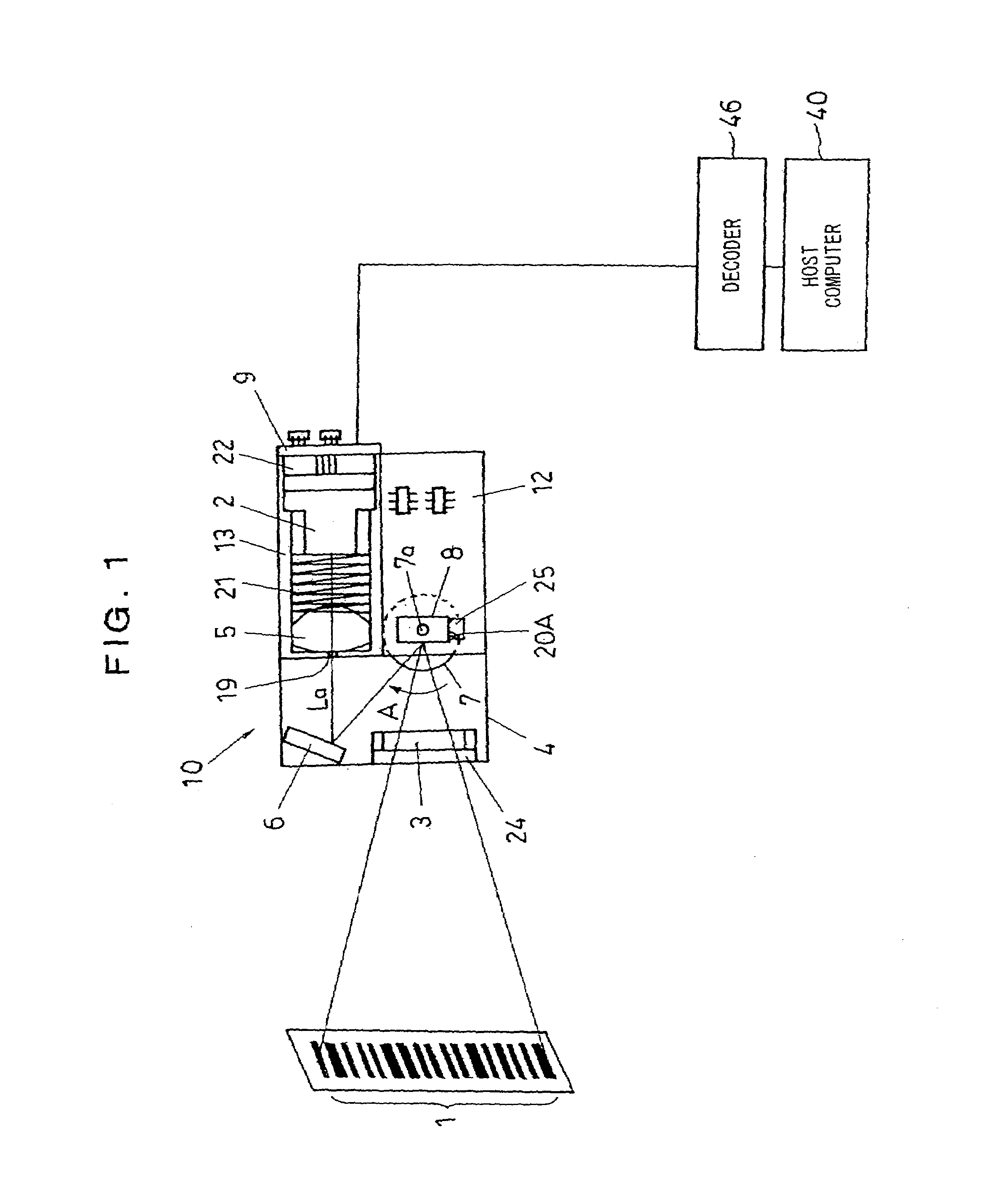
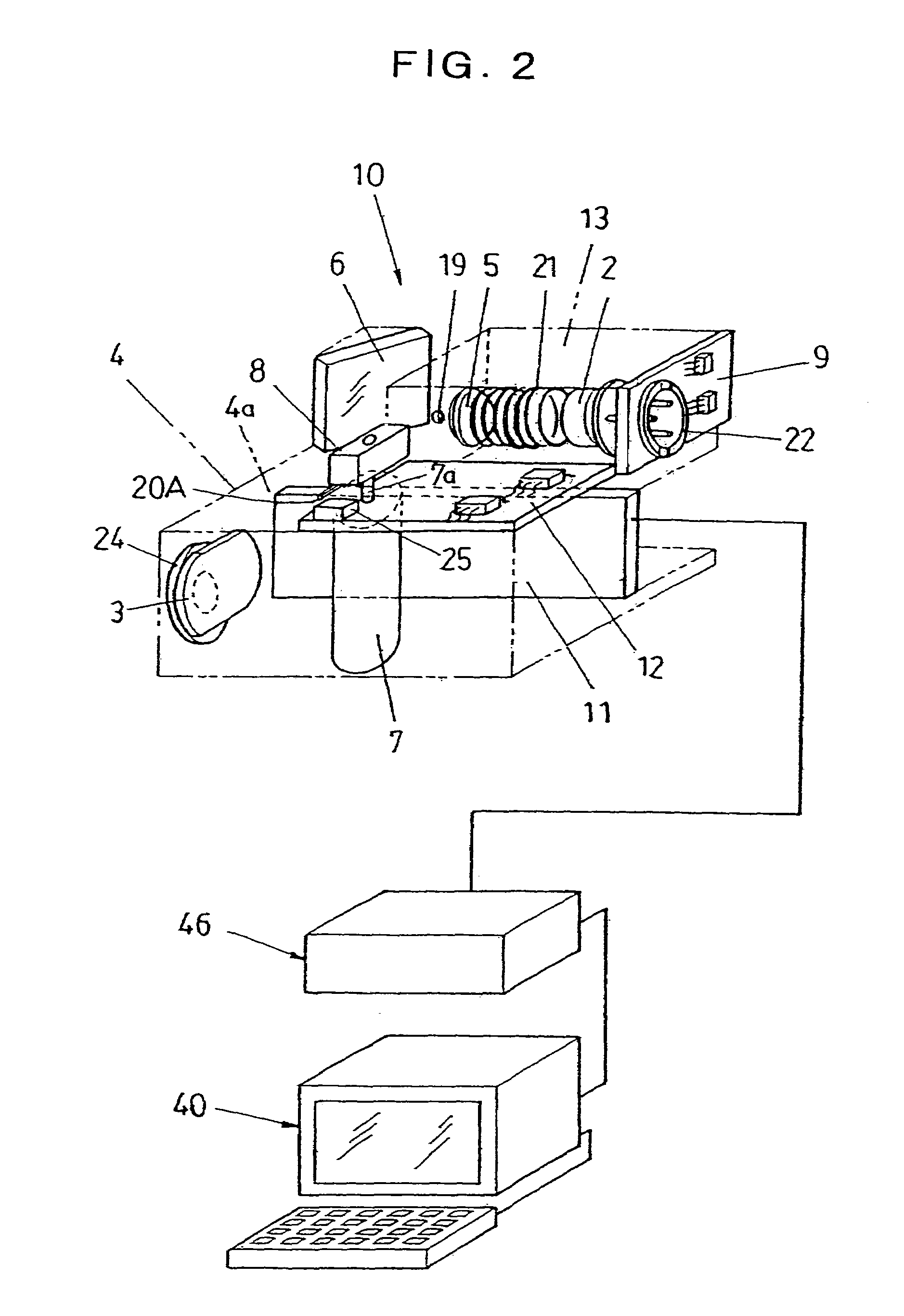
[0074]FIG. 1 is a schematic plan view of the first embodiment of the bar code reader according to the invention, showing a state of bar code reading, and FIG. 2 is a perspective view thereof, showing the constitution thereof in more details.

[0075]A scanning head 10 of the bar code reader is housed in a pen-type case (not shown), and as shown in FIG. 1, has a function of reading numerals and signs, as expressed by a combination of bars wider in width, bars narrower in width, and respective spacings between the bars adjacent to each other, making up a bar code 1, by applying a laser beam onto the bar code 1.

[0076]For that end, laser light emitted by a laser diode 2 is rendered into parallel light rays through a collimator lens 5, and a laser beam La in a thin beam for...

second embodiment

[0174]Next, a second embodiment of a bar code reader according to the invention is described with reference to FIGS. 28 to 32.

[0175]FIGS. 28 and 29 are a schematic plan view of the second embodiment of the bar code reader according to the invention, showing a state of bar code reading, and a perspective view thereof, showing the constitution thereof in more details, corresponding to FIGS. 1 and 2 for the previously-described first embodiment, respectively. FIG. 30 is a schematic plan view thereof, similar to FIG. 1, showing a state where rotation of a rotatory mirror 8 is temporarily stopped.

[0176]In these figures, parts corresponding to those in FIGS. 1 and 2 are denoted by the like reference numerals, and description thereof is omitted.

[0177]A scanning head 10B of the bar code reader differs in construction from the scanning head 10 of the previously-described first embodiment only in that fixed onto a retaining member 4 with a setscrew (not shown), respectively, are a mirror 6 wh...

third embodiment

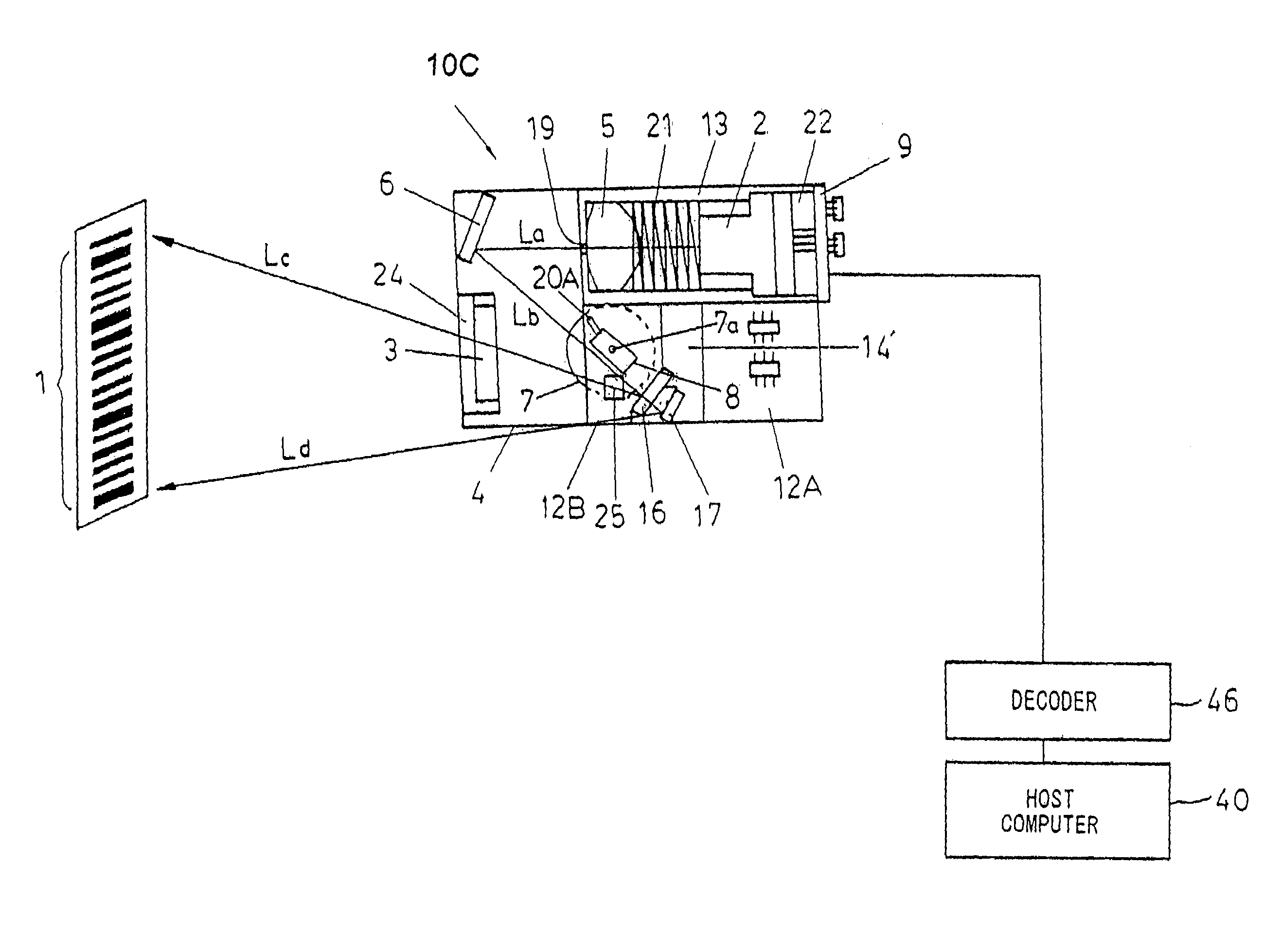
[0208]Next, a third embodiment of a bar code reader according to the invention is described with reference to FIGS. 33 to 35.

[0209]FIGS. 33, 34 and 35 are figures corresponding respectively to FIGS. 28, 29 and 30 showing the previously-described second embodiment. In these figures, parts corresponding to those in FIGS. 28, 29 and 30 are denoted by the like reference numerals, and description thereof is omitted.

[0210]As shown in FIGS. 33 and 34, a scanning head 10C of the bar code reader according to the third embodiment is provided with a translucent mirror 16 which is a translucent reflector, disposed so as to be supported by a mirror support member 14′, as a second fixed optical deflector in place of the previously-described mirror 15, and is further provided with a mirror 17 as a third fixed optical deflector, disposed behind the translucent mirror 16.

[0211]The translucent mirror 16 reflects a portion of an incoming laser beam to be deflected in a given direction, and allows the ...


PUM


Abstract

A bar code reader provided with a laser diode (2) and a rotatory mirror (8) for deflecting a laser beam emitted by the laser diode for scanning, wherein a strip (20A) attached to the rotatory mirror (8), serving as a sensing indicator, is sensed at a position corresponding to a reading start edge of a laser beam scanning range of a bar code (1), and rotation of the rotatory mirror (8) is stopped for a predetermined time length after sensing of the strip (20A) and measurement of a scanning time length up to the final position of bar code reading, respectively, in the case of automatic scanning while rotation of the rotatory mirror (8) is locked upon measurement of half of a scanning time length up to the final position of the bar code reading after the sensing of the strip (20A) in the case of manual scanning, so that the laser beam can be recognized with ease, enabling focusing thereof or the manual scanning to be implemented.

Description

RELATED APPLICATION[0001]This application is a divisional of U.S. patent application Ser. No. 09 / 867,710 filed on May 31, 2001, now U.S. Pat. No. 6,827,270, which is incorporated by reference in their entirety. Priority under 35 U.S.C. §§120 and 121 is hereby claimed for benefit of the filing date of U.S. patent application Ser. No. 09 / 867,710.BACKGROUND OF THE INVENTION[0002]1. Field of the Invention[0003]The present invention relates to a bar code reader for reading a bar code by applying a laser beam emitted from a laser diode to the bar code, and receiving reflected light therefrom through a photodetector.[0004]2. Description of the Related Art[0005]A bar code reader for reading a bar code by the agency of reflected light of light applied from a light source towards the bar code is in widespread use today in the distribution sector, sales control division, and so forth because of its capability of reading the bar code even if the bar code reader is at a good distance away from t...

Claims


Application Information

Patent Timeline
Patent Type & Authority Patents(United States)
IPC IPC(8): G06K7/10G02B26/00G06K7/14
CPCG06K7/10613G06K7/14
Inventor YOMOGIDA, MATSUOMATSUDA, HIDEAKI
Owner TOHOKU RICOH CO LTD
Why Eureka
Try Eureka