Fluoropolymer flowmeter

a fluoropolymer and flowmeter technology, applied in the direction of liquid/fluent solid measurement, volume metering, instruments, etc., can solve the problems of low and ultra-low fluid flow rate, deficiency of known float assemblies in the industry having a generally elongated float, and low fluid flow rate. , to achieve the effect of less contamination, mesurably translucent, and increased visibility of component positions

Inactive Publication Date: 2005-12-13
ENTEGRIS INC
View PDF19 Cites 5 Cited by
  • Summary
  • Abstract
  • Description
  • Claims
  • Application Information

AI Technical Summary

Benefits of technology

[0017]The embodiments of the flowmeter of the present invention substantially solve the problems innately present with conventional fluid flowmeters. These needs are addressed by introducing a corrosive-resistant flowmeter made of a material such as PFA where reliability and effectiveness are increased while manufacturing costs can be reduced in one embodiment by utilizing a unitary-bodied component construction. Further, the a functional component design that enables accurate and efficient readings and indications of reduced fluid flow rates.

Problems solved by technology

Due to their complexity, reliability and maintenance are issues, as is cost.
However, in certain industries, such as semi-conductor processing, low and ultra-low fluid flow rates are often required during processing.
Even known float assemblies in the industry having a generally elongate float, which are designed to meter low fluid flow rates, are deficient.
Such a system has an innate drawback in that stopping of the float 217 with the tapered section 218 within the bore or channel of guides 216 can cause an undesirable wedging effect.
This innate characteristic is particularly unacceptable when measuring low flow rates.
Since low flow rates are the focus of such a flowmeter, this can serve to decrease reliability and accuracy, especially for the periods of fluid flow prior to dislodging of the wedged float 217.
These fluids not only damage traditional flowmeter materials, but they additionally impose significant health risks for personnel exposed to the fluids during the manufacturing process.
These currently available fluoropolymer flowmeter devices, whether they be conventional sight tube flowmeters or other flowmeters, contain disadvantages centering mainly around the materials used and the methods of assembly.
Generally fluoropolymers, particularly PTFE, are not conducive to injection molding processes.
Moreover, multi-component flowmeter assemblies utilizing threaded portions present potential fluid leakage pathways.
The possibility of fluid leakage is increased with each non-unitary connection between components.
Such welding is not effective for joining tubular end portions.
Moreover, due to the “slippery” nature of fluoropolymers, forms of vibrating or oscillating bonding is not realistic.
Similarly, adhesives do not work on fluoropolymers, and would only add potential contaminants which must be avoided in semi-conductor processing applications.
Homogeneously joining by welding separate fluoropolymers components, such as PTFE, is essentially impossible.
All of the discussed prior art falls short of adequately addressing the unique accuracy, purity, and low fluid flow needs of the semi-conductor processing industry.
The prior art does not address the need for coupling the benefits PFA offers in resisting corrosion with the advantages a unitary-bodied component construction advances with regard to leakage prevention and reduced manufacturing and assembly costs.

Method used


Image

  • Fluoropolymer flowmeter
  • Fluoropolymer flowmeter
  • Fluoropolymer flowmeter

Examples


Embodiment Construction

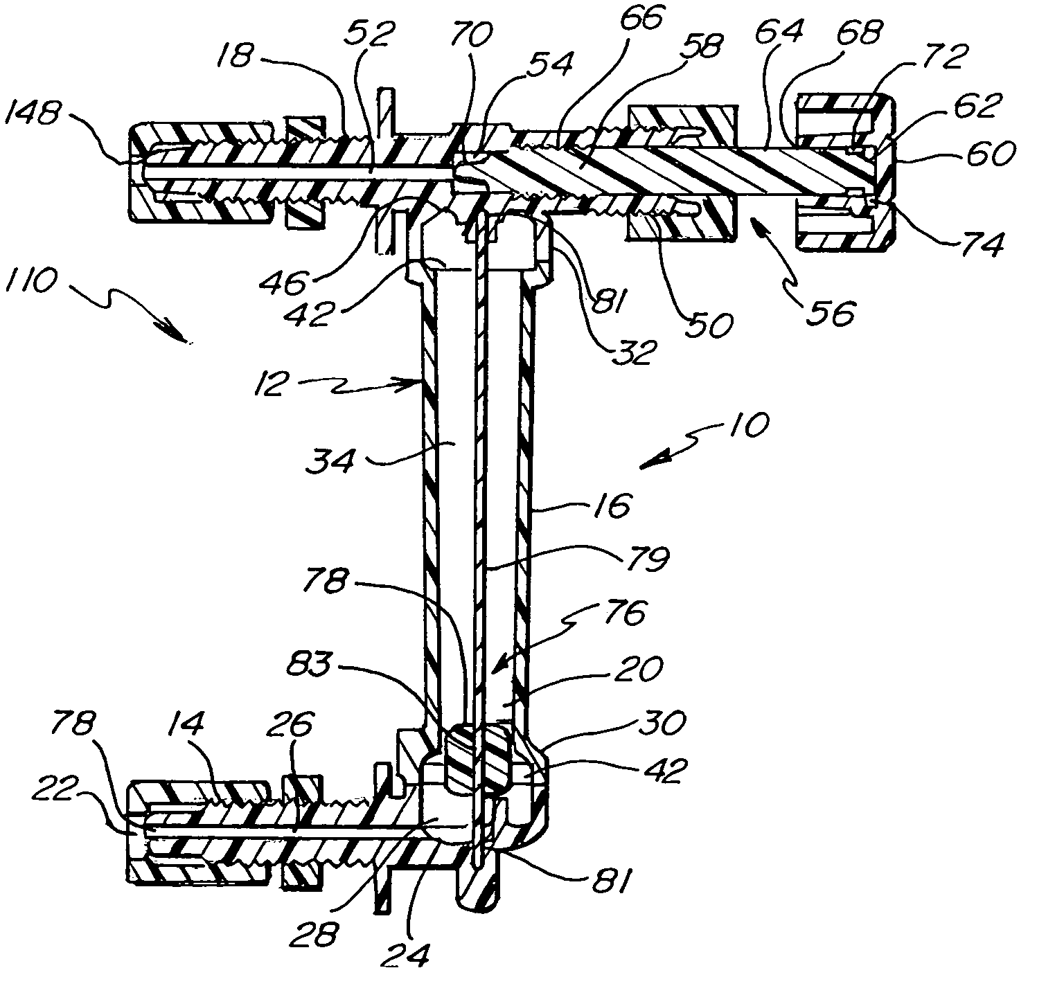
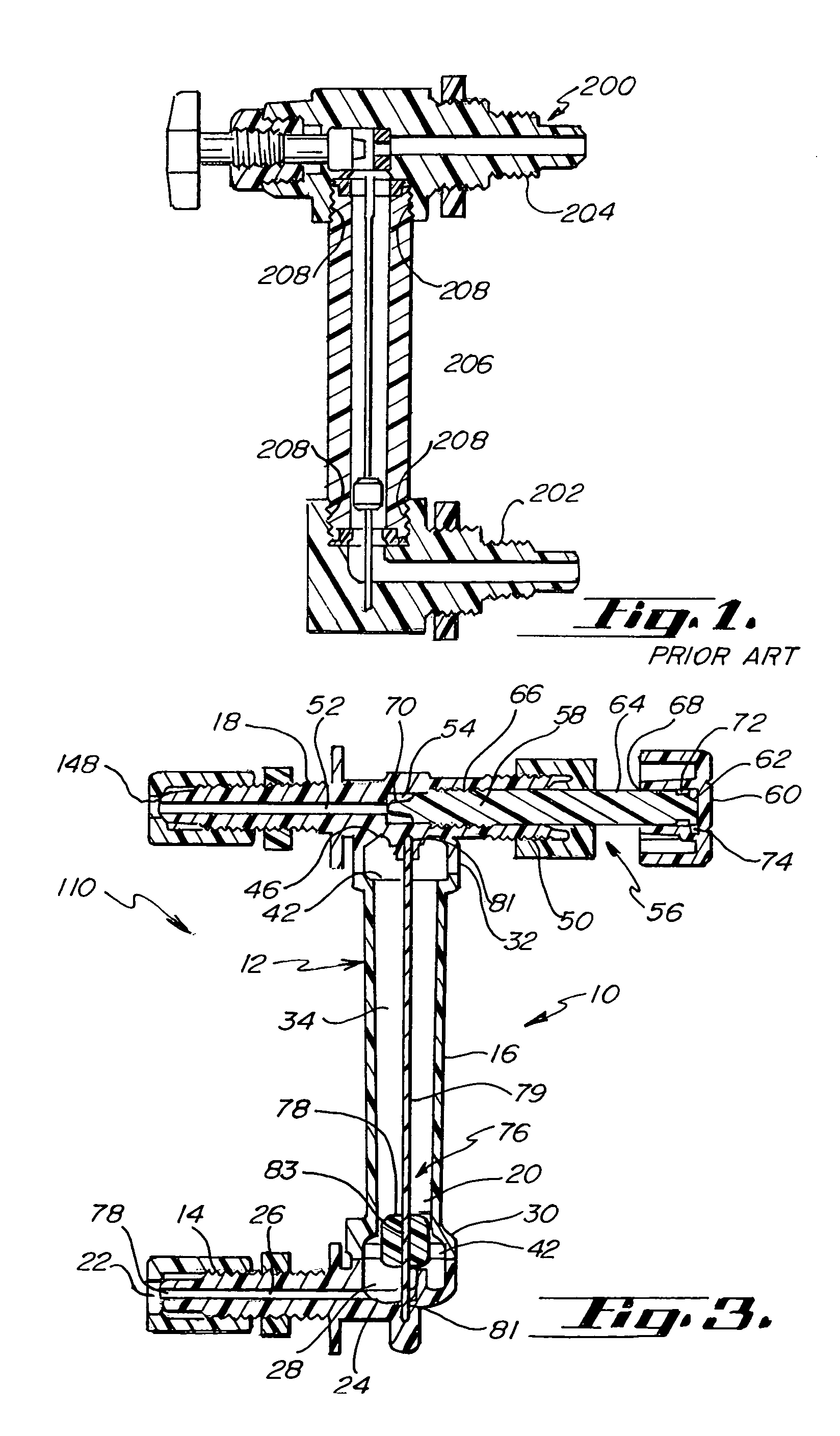
[0043]FIG. 3 shows one embodiment of a unitary-bodied flowmeter 12 in accordance with the present invention. The flowmeter can be a welded assembly of injection molded fluoropolymer plastic components, generally PFA components or fluoropolymers having translucent qualities, wherein at least two of the three main body components are joined through a compactable welding process. Other fluoropolymer plastics are also envisioned for component and part use in the flowmeters in accordance with the present invention. For example, but not for limiting purposes, PTFE, ETFE, and other plastics are envisioned. The translucent characteristics of the preferred fluoropolymers can vary in the degree to which it is translucent, such that translucent characteristics permit gauging of a float device within the sight tube, as will be discussed in detail herein.

[0044]Referring to FIGS. 3–10, flowmeter 10 generally comprises the joining of at least two of three main body components into a unitary flowme...


PUM

PropertyMeasurementUnit
temperatureaaaaaaaaaa
translucentaaaaaaaaaa
translucent propertiesaaaaaaaaaa

Abstract

In one embodiment, a sight tube flowmeter is formed of a plurality of fluoropolymer components welded together to form a unitary flowmeter body. The components can comprise a PFA upright sight tube having two end portions, a flow conduit extending therethrough and two fitting portions that are uniquely welded onto each end of the sight tube, and a fluoropolymer float device movable to various positions within the flow conduit depending on the flow level of the fluid flowing therethrough. The float device can be of conventional design or for those flowmeter embodiments where low fluid flow rates are to be measured, an elongate float can be utilized. The floats and, in particular, a designated portion thereof, are visible through the sight tube to provide visual indication of the position, and thus the flow rate of fluid flowing through the flowmeter. In addition, alternative embodiments include the implementation of the unique sight tube and elongate float design in conventional flowmeters.

Description

RELATED APPLICATIONS[0001]This is a divisional of U.S. patent application filed May 28, 2002, entitled “Fluoropolymer Flowmeter” and assigned Ser. No. 10 / 156,449, which in turn claims the benefit of the contents and filing date of U.S. Provisional Patent Application filed May 25, 2001, entitled “Injection Molded and Welded Fluoropolymer Flow Meters” and assigned Ser. No. 60 / 293,672, and Provisional Patent Application filed Mar. 15, 2002, entitled “Low Flow Rate Fluoropolymer Flowmeter” and assigned Ser. No. 60 / 364,774, with all of said applications being incorporated herein by reference.FIELD OF THE INVENTION[0002]This invention relates generally to fluid flowmeters, and more particularly, to a substantially unitary-bodied fluoropolymer flowmeter capable of employing various component and float configurations.BACKGROUND OF THE INVENTION[0003]Flowmeters are utilized in many different industries to measure and control the flow of various fluids. Flowmeters generally utilize moveable f...

Claims


Application Information

Patent Timeline
Patent Type & Authority Patents(United States)
IPC IPC(8): B29C45/26B29C65/14G01F1/22G01F15/00
CPCB29C66/1142G01F1/22G01F15/006B29C65/1432B29C66/543B29C66/71B29C45/261Y10T29/49004B29K2027/12B29K2995/0029B29C66/52241B29C66/52231B29C66/5224B29C65/00B29C66/73921B29C66/73365
Inventor LEYS, JOHN A.KOLBOW, STEVEN P.FISCHER, STEVEN A.CADAVID, CARLOSULSCHMID, TODD M.
Owner ENTEGRIS INC
Why Eureka
Try Eureka