
Packaging for semiconductor laser device and method for producing the same

a laser device and semiconductor technology, applied in semiconductor lasers, semiconductor/solid-state device details, optical beam sources, etc., can solve the problem of reducing the effect of the deviation angle of the optical axis of the semiconductor, increasing the area of the reference plane accordingly, and preventing the deterioration of the welded portions

Inactive Publication Date: 2006-04-25
SHARP KK
View PDF5 Cites 5 Cited by
  • Summary
  • Abstract
  • Description
  • Claims
  • Application Information

AI Technical Summary

Benefits of technology

[0013]An object of this invention is to provide a semiconductor laser device which can secure a sufficient area for a reference plane in view of retaining precision in optical characteristics and which can also cope with changes in environmental humidity, and to provide a method for producing the same.

Problems solved by technology

Therefore, even with the same degree of unevenness in the reference plane, an increase in the area of the reference plane accordingly reduces the effect on the deviation angle θ of the optical axis of the semiconductor laser element from the normal line to the reference plane of the optical pickup.

Method used


Image

  • Packaging for semiconductor laser device and method for producing the same
  • Packaging for semiconductor laser device and method for producing the same
  • Packaging for semiconductor laser device and method for producing the same

Examples


Embodiment Construction

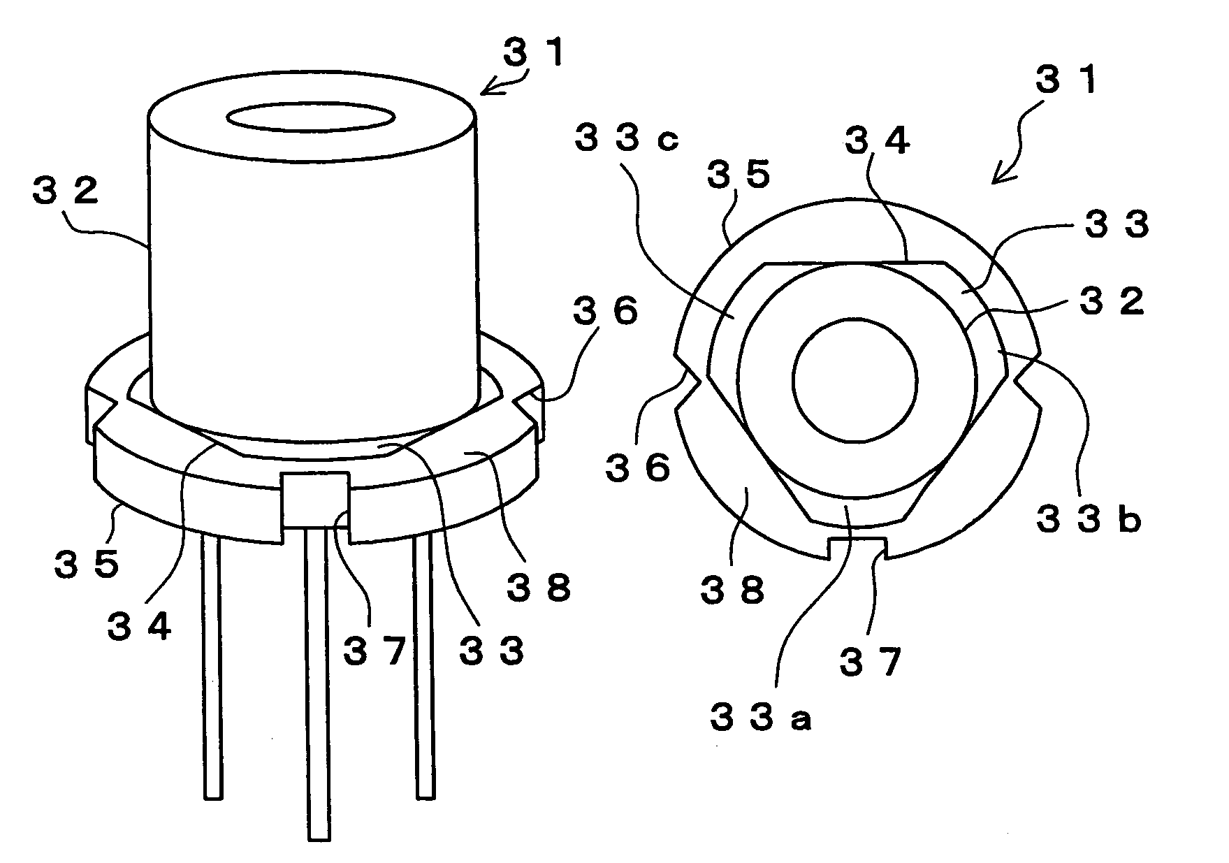
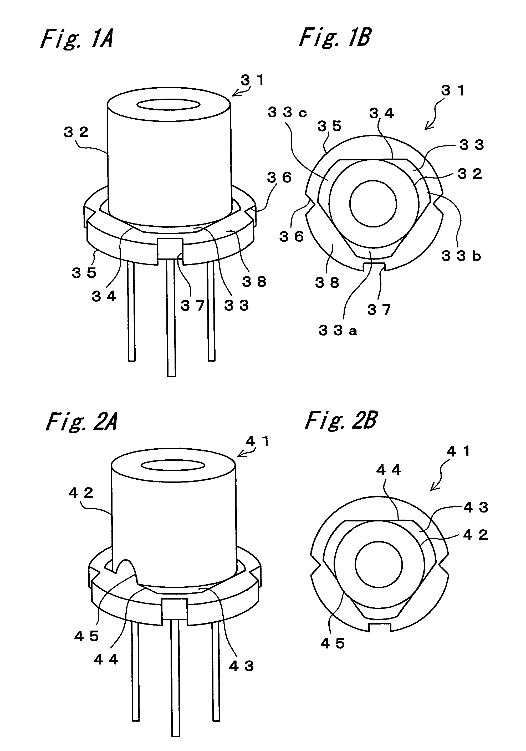
[0038]The present invention will hereinafter be described in detail by way of examples illustrated. FIG. 1A and FIG. 1B are external views of a semiconductor laser device of an embodiment of the present invention. FIG. 1A is a perspective view, and FIG. 1B is a plan view. In the semiconductor laser device 31 according to the present embodiment, a flange 33 provided circumferentially at a lower-edge portion of a cap 32 is formed into a shape having three cut-off portions 34 formed by cutting off three portions along respective straight lines from a ring or annulus shape with a constant width. The flange 33 of the cap 32 is positioned or aligned with respect to a circular stem 35 having two V-shaped notches and one U-shaped notch, totally three notches, so that the cut-off portions 34 of the flange 33 substantially do not overlap the notches 36, 37 of the stem 35 in position. Then, welding is performed.

[0039]Thus, welding is carried out in a state that the cut-off portions 34 of the f...


PUM


Abstract

In a semiconductor laser device, a flange (33) of a cap (32) is provided with straight-line cut-off portions (34) that are the same in number as notches (36, 37) of a stem (35). With the cut-off portions (34) positioned so as not to overlap the notches (36, 37) of the stem (35) in position, welding between the cap (32) and the stem (35) is performed. The cut-off portions (34) of the cap (32) secure obtainment of a reference plane 38 with a large area in a place where the notches (36, 37) of the stem (35) are absent. As a result, sufficient precision in optical characteristics can be secured while suppressing an influence of unevenness of the stem (35) having a small diameter on a deviation angle θ of an optical axis from a normal line to a reference plane of an optical pickup.

Description

BACKGROUND OF THE INVENTION[0001]The present invention relates to a semiconductor laser device that is used for an optical recording information device such as CD-ROM, CD-R / RW, MO and DVD, and a method for producing the same.[0002]As a semiconductor laser device in which a semiconductor laser element is mounted on a stem, there has hitherto been one shown in FIGS. 4A and 4B. FIG. 4A is a perspective view showing the exterior of the device, and FIG. 4B is a longitudinal cross-sectional view thereof. A semiconductor laser element 1 and a monitoring photodiode (not shown) are die bonded to a submount 4 of a stem 3 and they are connected to lead pins 6 using Au wires 5. Further, a cap 8 is welded to the stem 3 by electric welding, and for the purpose of protecting the semiconductor element from dust from outside, external stress and / or optical interference, the cap 8 is provided with a window opening 7 letting laser beams pass therethrough (e.g., see JP-2000-252575A).[0003]Welding betwe...

Claims


Application Information

Patent Timeline
Patent Type & Authority Patents(United States)
IPC IPC(8): H01S3/04H01L23/10H01L29/24H01S3/00H01S5/022
CPCG11B7/127H01S5/02212H01S5/0222H01L2224/48247H01L2224/45144H01L2924/00
Inventor CHIKUGAWA, HIROSHI
Owner SHARP KK
Learn More