
Radiation window and method of manufacture

a technology of a radiation window and a manufacturing method, which is applied in the manufacture of electrode systems, electrical discharge tubes/lamps, nuclear engineering, etc., can solve the problems of preventing the transmission of soft x-rays, the window is thin and the operation and longevity of x-ray detectors and x-ray emitters are seriously affected, and the leakage of thin beryllium windows is difficult to achieve without leaving a leakage hol

Inactive Publication Date: 2006-04-25
MOXTEK INC
View PDF31 Cites 58 Cited by
  • Summary
  • Abstract
  • Description
  • Claims
  • Application Information

AI Technical Summary

Benefits of technology

The invention provides a window device that can be used at high temperatures, maintain a vacuum, and transmit soft x-rays. The window includes a support with an opening for transmitting radiation, a film mounted on the support, and a coating covering the film and support. The film is made of beryllium and has a thickness of less than 23 micrometers. The adhesive is a polymeric material, and the coating is a boron-hydrogen composition. The method involves applying a liquid adhesive to the film and support, curing the adhesive at a temperature greater than 250 degrees Celsius, and applying a substantial vacuum to assist in the curing process. The exposed portion of the film is coated with an organic material on at least one side of the film. The technical effects of the invention include improved performance at high temperatures, better vacuum maintenance, and improved soft x-ray transmission.

Problems solved by technology

In the vacuum chamber, even minute amounts of gas pose a serious threat to the operation and longevity of x-ray detectors and x-ray emitters.
Unfortunately, the thickness of the window prevents transmission of the soft x-rays emitted by sodium and elements with even lower atomic numbers (Z).
Thinner beryllium windows have proven difficult to attach to support structures without leaving leaks in the resulting assembly.
In addition, beryllium windows can develop leaks if its mounting promotes stress concentration.
The window can be subjected to heat during mounting or during use.

Method used


Image

  • Radiation window and method of manufacture
  • Radiation window and method of manufacture
  • Radiation window and method of manufacture

Examples


Embodiment Construction

[0017]Reference will now be made to the exemplary embodiments illustrated in the drawings, and specific language will be used herein to describe the same. It will nevertheless be understood that no limitation of the scope of the invention is thereby intended. Alterations and further modifications of the inventive features illustrated herein, and additional applications of the principles of the inventions as illustrated herein, which would occur to one skilled in the relevant art and having possession of this disclosure, are to be considered within the scope of the invention.

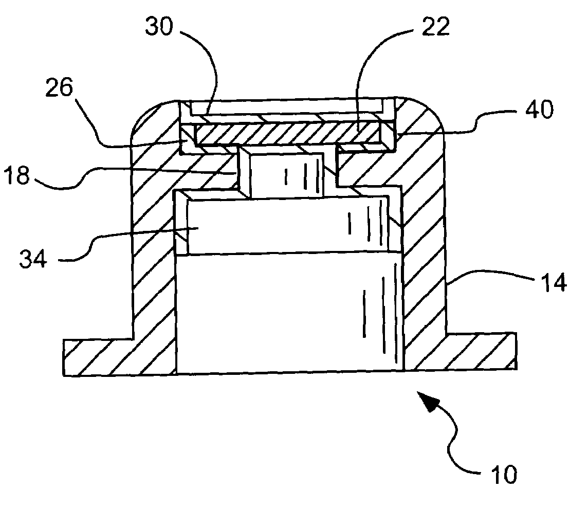
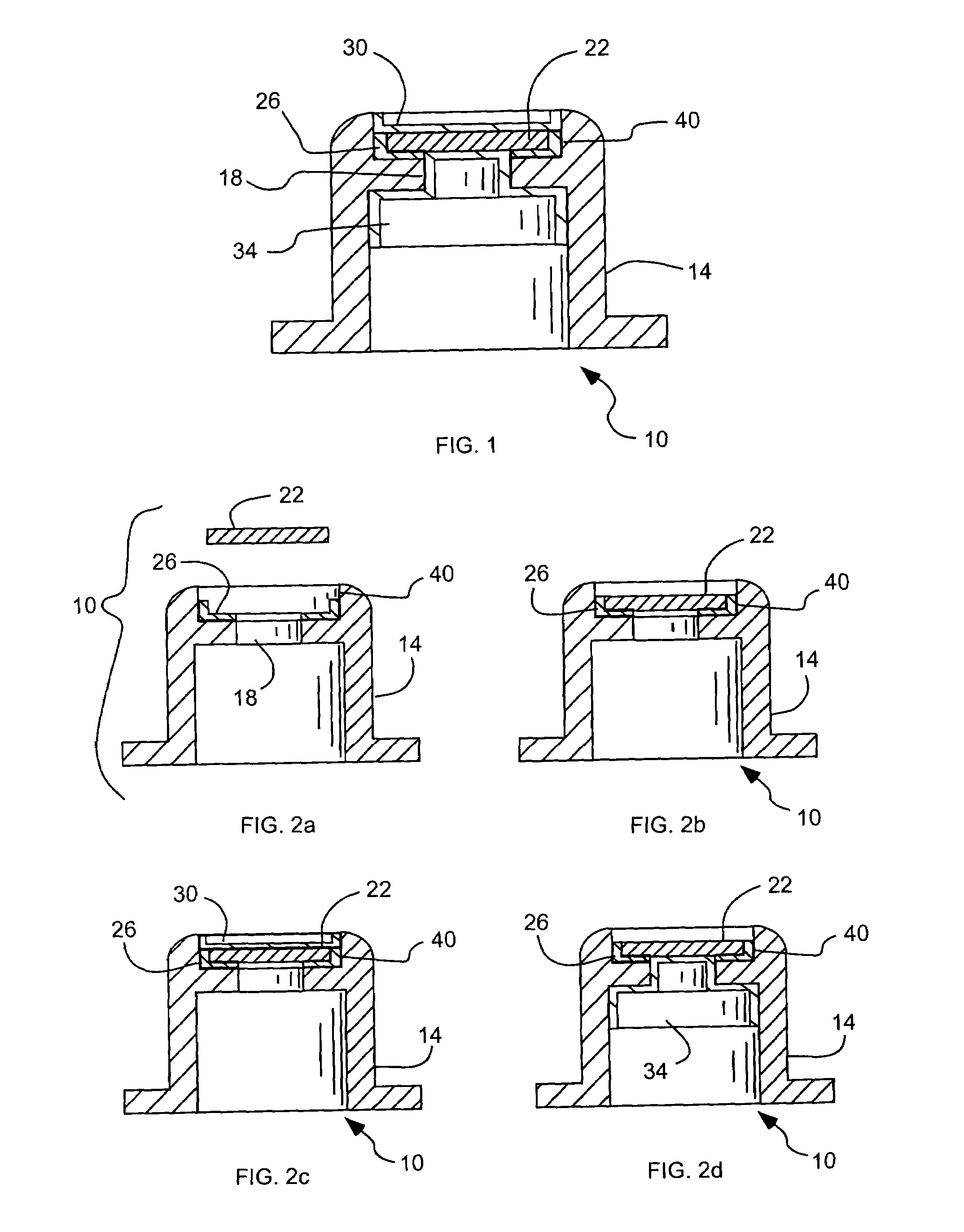
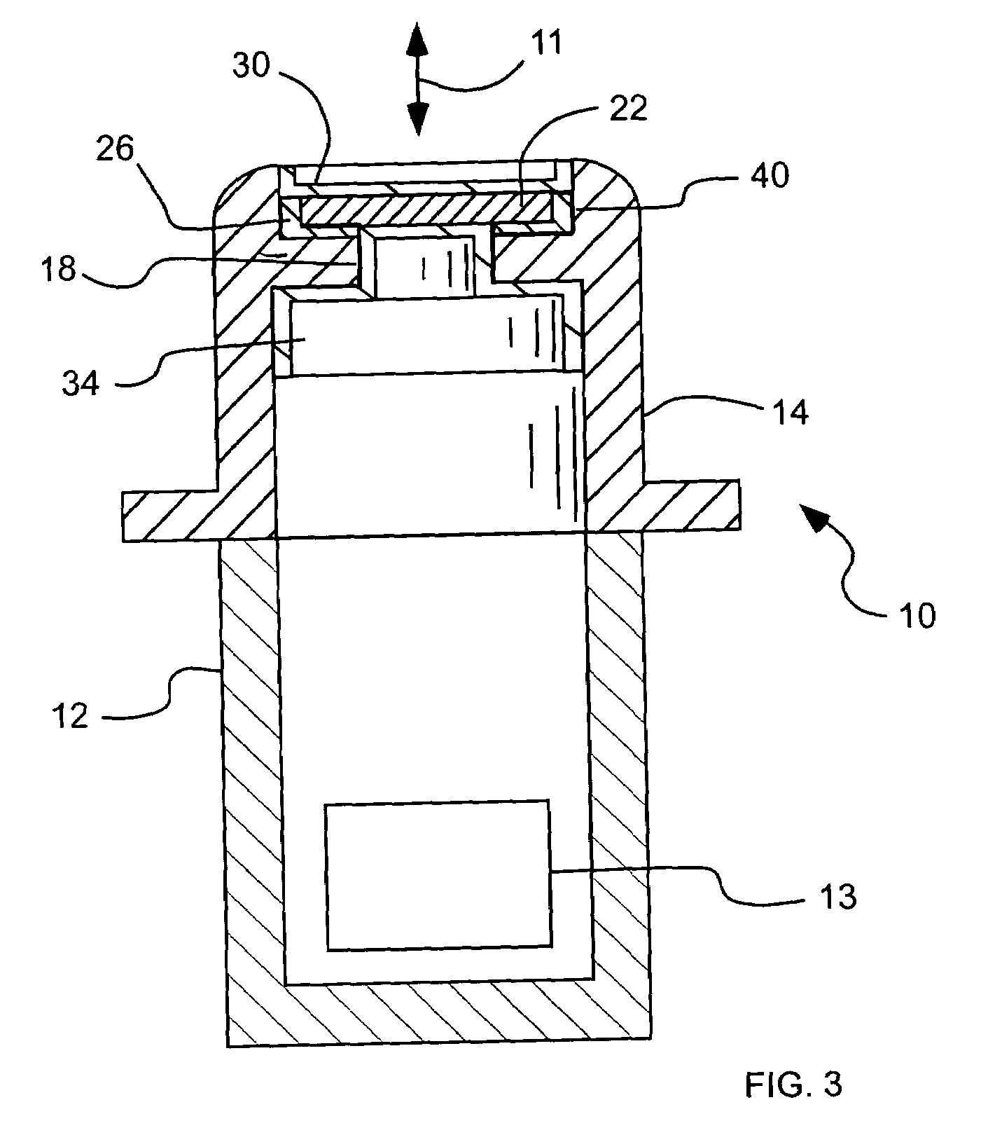
[0018]As illustrated in FIGS. 1–3, a radiation window, device or assembly, indicated generally at 10, in accordance with the present invention is shown for transmitting electrons or radiation (represented by line 11 in FIG. 3) while sealing a vacuum chamber or evacuated chamber 12. Thus, the radiation window 10 can be utilized as part of an x-ray source or an x-ray detector 13 (FIG. 3). X-ray sources and detector...


PUM


Abstract

A radiation window device to transmit radiation as part of an x-ray source or detector includes a support to be subject to a substantial vacuum, and an opening configured to transmit radiation. A film is mounted directly on the support across the opening, and has a material and a thickness selected to transmit soft x-rays. An adhesive directly adheres the film to the support. A coating covers exposed portions of at least one of the evacuated or ambient sides of the film, and covers a portion of the support surrounding the film. The support, film and adhesive form a vacuum tight assembly capable of maintaining the substantial vacuum when one side is subject to the substantial vacuum. In addition, the vacuum tight assembly can withstand a temperature of greater than approximately 250 degrees Celsius.

Description

[0001]This application claims the benefit of U.S. Provisional Patent Application No. 60 / 410,517, filed Sep. 13, 2002.BACKGROUND OF THE INVENTION[0002]1. Field of the Invention[0003]The present invention relates generally to a window for sealing a vacuum chamber and transmitting radiation or electrons.[0004]2. Related Art[0005]X-ray sources or x-ray detectors utilize a vacuum chamber with a window through which x-rays are transmitted. The window can be formed of beryllium foil that is typically made by rolling. The rolling can produce a mosaic of crystallites with grain boundaries that can leak gas. In the vacuum chamber, even minute amounts of gas pose a serious threat to the operation and longevity of x-ray detectors and x-ray emitters. Beryllium windows are typically made relatively thick (greater than about 23 μm) to prevent leaks. Unfortunately, the thickness of the window prevents transmission of the soft x-rays emitted by sodium and elements with even lower atomic numbers (Z)....

Claims


Application Information

Patent Timeline
Patent Type & Authority Patents(United States)
IPC IPC(8): H01J35/18H01J9/24G21K1/10G21K5/04H01J5/18H01J5/24H01J9/26H01J33/04
CPCG21K1/10G21K5/04H01J5/18H01J9/26H01J33/04H01J35/18H01J5/24H01J2235/183
Inventor TURNER, D. CLARKDECKER, KEITH W.ROBERTS, M. CHRISTINESTILLWELL, ROBERT N.
Owner MOXTEK INC
Learn More