Image conversion and encoding techniques

a technology of encoding and conversion, applied in the field of image conversion and encoding techniques, can solve the problems of slow process, time-consuming and costly, slow, tedious, time-consuming and expensive process, etc., and achieve the effect of reducing the number of frames, reducing the time commitment of operators, and acceptable results

Inactive Publication Date: 2006-04-25
DYNAMIC DIGITAL DEPTH RES
View PDF7 Cites 72 Cited by
  • Summary
  • Abstract
  • Description
  • Claims
  • Application Information

AI Technical Summary

Benefits of technology

[0014]Presently, it is necessary for an operator to manually create a depth map for each frame of an image, so as to obtain acceptable results. It is an object of the present invention to reduce the number of frames that require manual depth creation, thereby reducing the time commitments for operators creating the depth maps.
[0045]The algorithm then applies this learned relationship to the remaining pixels in the image to generate a depth map. If necessary, the user can refine their data to improve the accuracy of the depth map. It should be noted that the initial depth data need not necessarily be specified by a user—it may be determined by some other process including, but not limited to using an automated structure from motion algorithm or deriving depth estimates from stereo images.

Problems solved by technology

This process is understandably slow, time consuming and costly.
It will be appreciated that this is a slow, tedious, time consuming and expensive process.
The main limitation of this approach is the need to teach the software implementing the technique the expected motion of the object being tracked.
This is a significant limitation when either the expected motion is not known, complex deformations are anticipated, or numerous objects with different motion characteristics are required to be tracked simultaneously.
However, their application is very limited because it is frequently impossible to identify a suitable tracking point whose motion reflects the motion of the object as a whole.
Point tracking is sometimes acceptable when objects are undergoing simple translations, but will not handle shape deformations, occlusions, or a variety of other common problems.
The product relies on tracking the colour of an object and thus fails when similar coloured objects intersect.
The product also has difficulty tracking objects that change in size over subsequent frames, for example, as an object approaches a viewer or moves forward on the screen.
None of these approaches are able to acceptably assign, nor track, depth maps, and thus the creating of the depth maps is still a manual system.
The limitation of these techniques is the need for camera motion within the original image sequence and the presence of well-defined features within each frame that can be used as tracking points.

Method used


Image

  • Image conversion and encoding techniques
  • Image conversion and encoding techniques
  • Image conversion and encoding techniques

Examples


embodiment

Preferred Embodiment

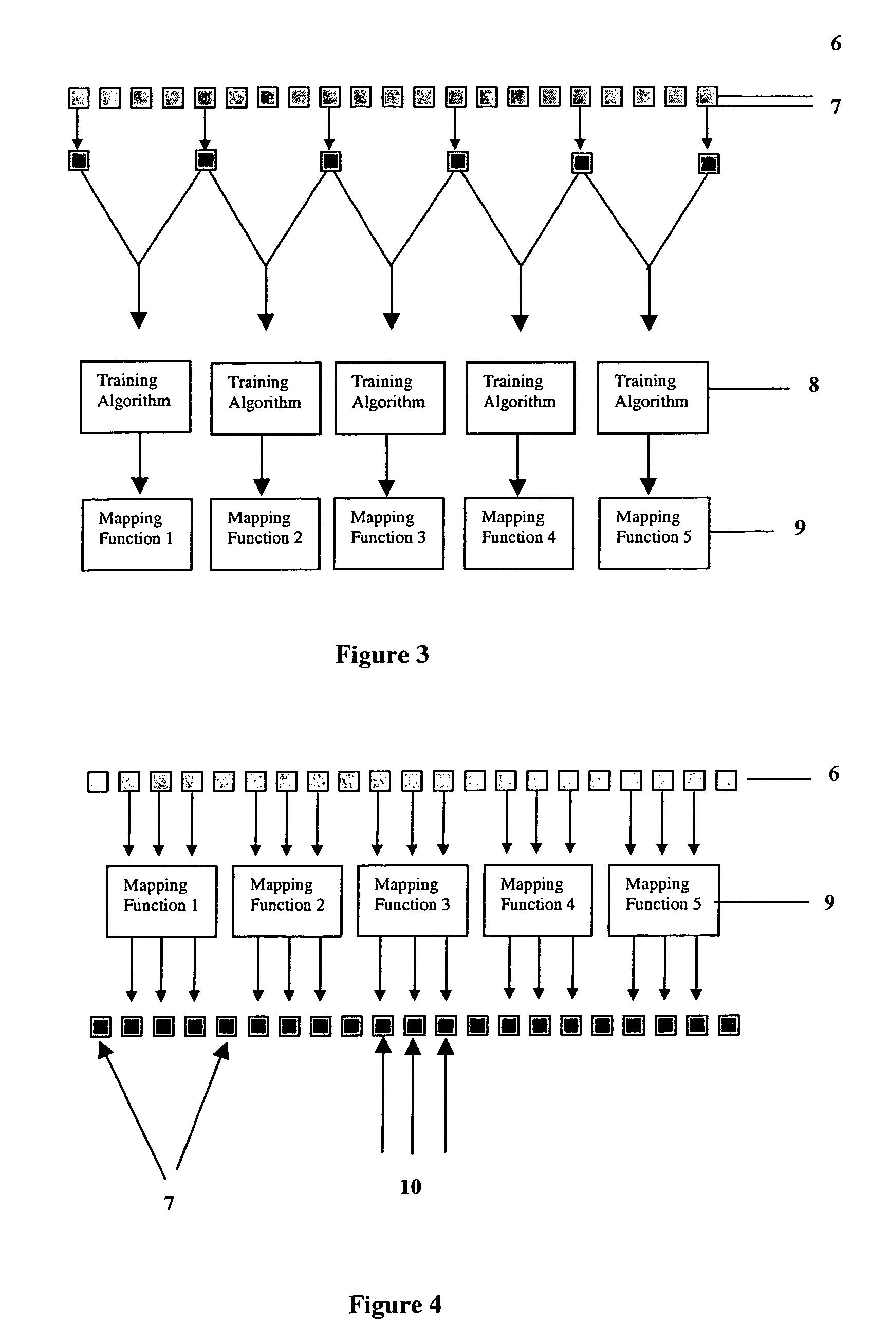
[0131]For each pixel in the frame to be depth mapped the image characteristics of the target pixel are used to determine the depth associated with the said pixel. In the preferred embodiment two depth estimates are retrieved, one from each key frame. This process is illustrated in FIG. 7, which shows how a target pixel 11 is compared to the closest source key frame 6 before and after the current frame in the image sequence (step 12 and 13). The learning process, similar to that described previously uses a search radius 14 to identify pixels with similar image characteristics and uses the depth associated with the said pixels (step 15 and 16) to calculate a depth for the target pixel (step 17 and 18). Each key frame generates an estimate of the target pixel's depth, which we will define as D1 and D2.

[0132]To determine a final depth associated with the target pixel the depths D1 and D2 must be combined. In the preferred embodiment a weighted average of these values...


PUM


Abstract

A method of creating a depth map including the steps of assigning a depth to at least one pixel or portion of an image, determining relative location and image characteristics for each at least one pixel or portion of the image, utilizing the depth(s), image characteristics and respective location to determine an algorithm to ascertain depth characteristics as a function relative location and image characteristics, utilizing said algorithm to calculate a depth characteristic for each pixel or portion of the image, wherein the depth characteristics form a depth map for the image. In a second phase of processing the said depth maps form key frames for the generation of depth maps for non-key frames using relative location, image characteristics and distance to key frame(s).

Description

CROSS-REFERENCE TO RELATED APPLICATIONS[0001]This application is based upon and claims the benefit of priority from the prior Australian Patent Application Nos. PQ9292, filed Aug. 9, 2000, and PR0455, filed Sept. 29, 2000, the entire contents of which are incorporated herein by reference.FIELD OF THE INVENTION[0002]The present invention is an improved technique for deriving depth maps from one or more 2D images.BACKGROUND OF THE INVENTION[0003]A number of image processing tasks require that the depth of objects within an image be known. Such tasks include the application of special effects to film and video sequences and the conversion of 2D images into stereoscopic 3D. Determining the depth of objects may be referred to as the process of creating a depth map. In a depth map each object is coloured a shade of grey such that the shade indicates the depth of the object from a fixed point. Typically an object that is distant will be coloured in a dark shade of grey whilst a close objec...

Claims


Application Information

Patent Timeline
Patent Type & Authority Patents(United States)
IPC IPC(8): G06K9/00G06T5/00G06T17/40G06T7/00G06T15/70
CPCG06T7/0053G06T7/0071H04N13/0022G06T2207/20081G06T2207/20092G06T2207/10016G06T7/507G06T7/579H04N13/128G06T19/00
Inventor HARMAN, PHILIP VICTORFOX, SIMON RICHARDDOWLEY, MARK ROBERTFLACK, JULIEN CHARLES
Owner DYNAMIC DIGITAL DEPTH RES
Why Eureka
Try Eureka