Eureka AIR delivers breakthrough ideas for toughest innovation challenges, trusted by R&D personnel around the world.

Method and apparatus for optimizing cache hit ratio in non L1 caches

Active Publication Date: 2006-04-25
IBM CORP
View PDF54 Cites 40 Cited by
  • Summary
  • Abstract
  • Description
  • Claims
  • Application Information

AI Technical Summary

Benefits of technology

[0023]To overcome the limitations in the prior art described above, and to overcome other limitations that will become apparent upon reading and understanding the present specification, the present invention discloses a method and apparatus for increasing processor performance in a computing system.
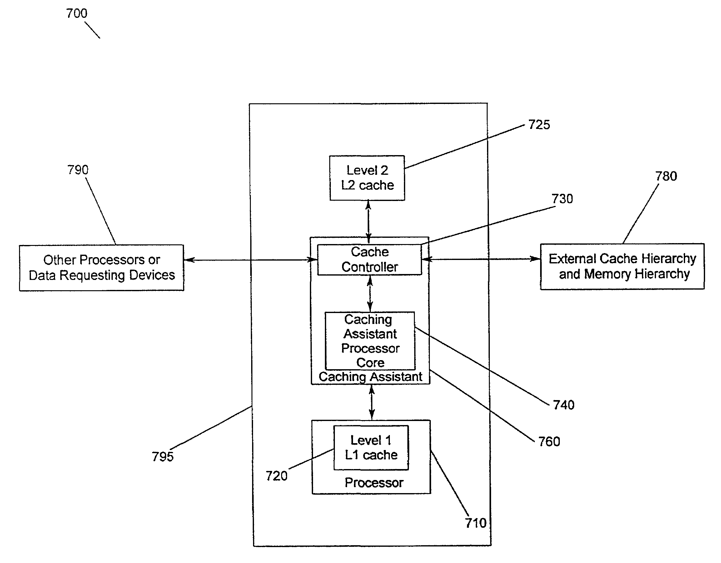
[0026]In another embodiment of the present invention, a computing system includes at least one processor, a memory that includes a cache hierarchy, and a caching assistant, wherein the caching assistant includes a cache controller for analyzing system activity and a memory, wherein the caching assistant increases processor performance by optimizing the hit ratio of at least one non-L1 cache.
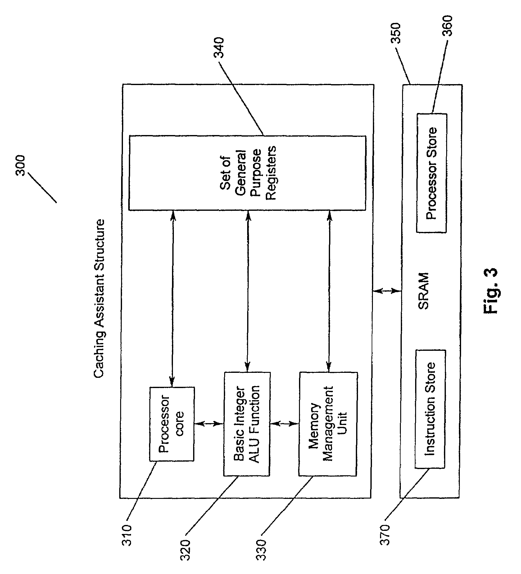
[0027]In another embodiment of the present invention, a caching assistant includes a cache controller for analyzing system activity and a cache dedicated to the caching assistant, wherein the caching assistant increases processor performance by optimizing the hit ratio of at least one non-L1 cache.

Problems solved by technology

However, if the access is not already present and available in the cache, this is considered a miss.
That is, if L1 caches run at processor speeds and have the capacity to contain the entire code load, including all necessary peripheral data and instructions, then the resulting processing time would be the smallest time possible.
However, the reality is that modern code loads for complex programs and systems are very large, often many megabytes.
Therefore, it is impractical to provide processors with embedded L1 caches having such large capacities.
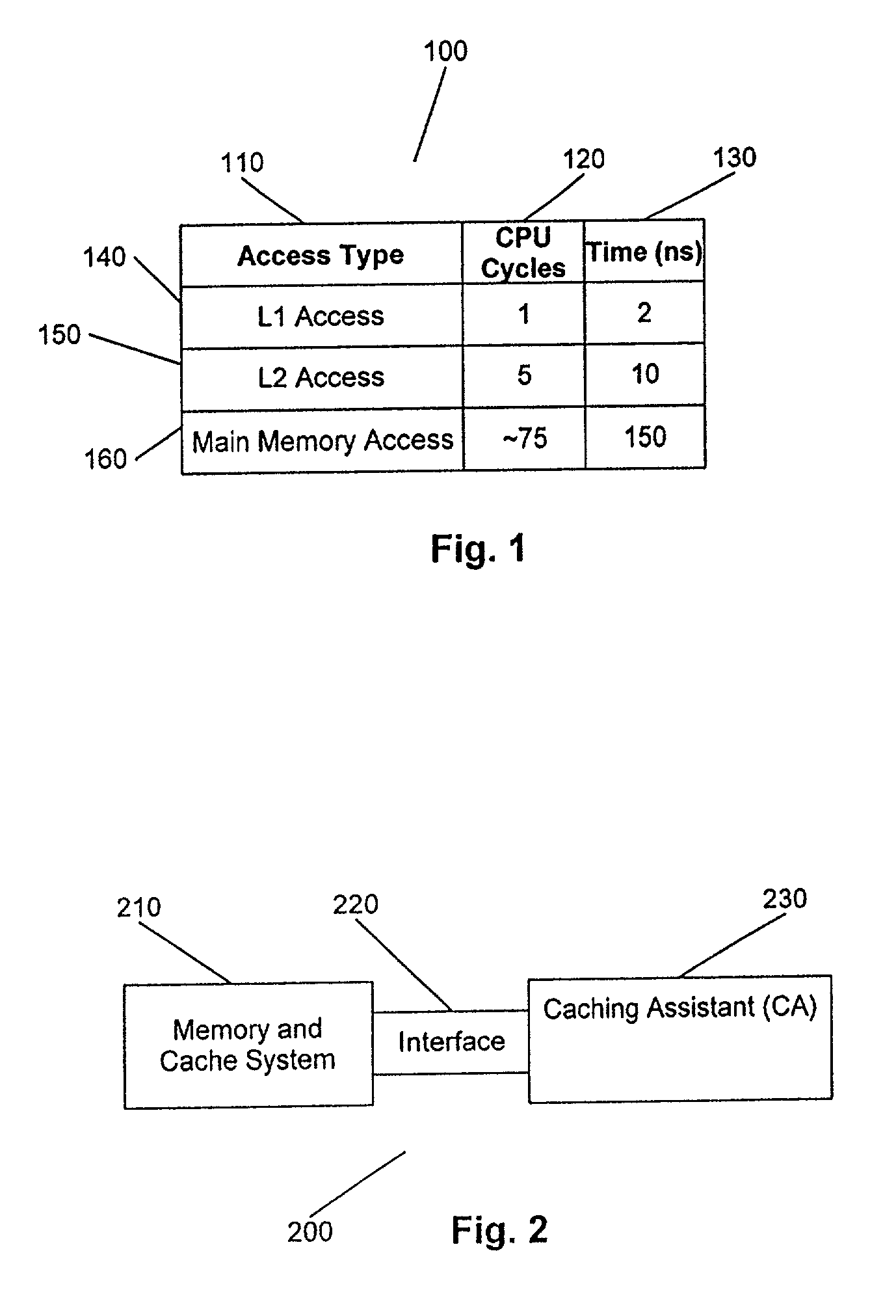
For example, practical constraints have limited L1 caches in processors to 32K bytes or less in most cases.
Instruction hit ratios, using economically feasible L1 capacities currently available, have tended to be disappointingly low.
Unfortunately, many L2 subsystems are only 2 way set associative.
Therefore, due to size limitations and the type of L2 cache, the misses may still represent a sizable portion of the fetches done by the processor.
A miss will result in fetching from the next level of memory in the memory hierarchy.
When designing complex systems there are also competing design constraints.
In such environments, there are power and cost considerations which often prevent the use of the fastest processors available in servers or desktop PCs.
For these environments where space, cost and power are limitations, the system designers are faced with very limited options regarding how to minimize main memory accesses while meeting the power dissipation and cost budgets and also meeting physical space constraints.
Unfortunately, such algorithms do not have access to information such as: how often a certain cache line is fetched, does a particular address seem to get cast out frequently, what addresses are likely to get accessed once a given address has been fetched.
Such information is very difficult to manage and make decisions upon given traditional caching hardware.
However, an external cache controller is severely disadvantaged in performing the function of controlling the internal and external cache memory of a processor.
Because the cache controller is located external to the processor and at some distance from the processor, the cache controller is unable to operate at processor speeds.
The result is that the CPU may encounter stalls in its pipeline as latency increases.

Method used


Image

  • Method and apparatus for optimizing cache hit ratio in non L1 caches
  • Method and apparatus for optimizing cache hit ratio in non L1 caches
  • Method and apparatus for optimizing cache hit ratio in non L1 caches

Examples


Embodiment Construction

[0045]In the following description of the exemplary embodiment, reference is made to the accompanying drawings which form a part hereof, and in which is shown by way of illustration the specific embodiment in which the invention may be practiced. It is to be understood that other embodiments may be utilized as structural changes may be made without departing from the scope of the present invention.

[0046]The present invention provides a method and apparatus for optimizing the hit ratio of at least one non-L1 cache operatively connected to a processor by providing a caching assistant to go along with the cache controller which provides cache analysis and cache maintenance. The method and apparatus is applicable to processors having embedded L2 caches, embedded L3 caches, external L2 caches, external L3 caches, etc., and other special purpose caches. It is also applicable to processors having embedded L1 caches to optimize a hit ratio of at least one non-L1 cache. Caching assistant fir...


PUM


Abstract

A method and apparatus for increasing the performance of a computing system and increasing the hit ratio in at least one non-L1 cache. A caching assistant and a processor are embedded in a processing system. The caching assistant analyzes system activity, monitors and coordinates data requests from the processor, processors and other data accessing devices, and monitors and analyzes data accesses throughout the cache hierarchy. The caching assistant is provided with a dedicated cache for storing fetched and prefetched data. The caching assistant improves the performance of the computing system by anticipating which data is likely to be requested for processing next, accessing and storing that data in an appropriate non-L1 cache prior to the data being requested by processors or data accessing devices. A method for increasing the processor performance includes analyzing system activity and optimizing a hit ratio in at least one non-L1 cache. The caching assistant performs processor data requests by accessing caches and monitoring the data requests to determine knowledge of the program code currently being processed and to determine if patterns of data accession exist. Based upon the knowledge gained through monitoring data accession, the caching assistant anticipates future data requests.

Description

CROSS-REFERENCE TO RELATED APPLICATION[0001]This application is related to the following co-pending and commonly-assigned U.S. Patent Application, which is hereby incorporated herein by reference in their respective entirety:[0002]“METHOD AND APPARATUS PROVIDING NON LEVEL ONE INFORMATION CACHING USING PREFETCH TO INCREASE A HIT RATIO” to Azevedo et al., having U.S. patent application Ser. No. 10 / 153,966 filed on May 22, 2002.BACKGROUND OF THE INVENTION[0003]1. Field of the Invention[0004]This invention relates in general to processor caching methods, and more particularly to a method and apparatus for increasing processor performance in a computing system by optimizing the hit ratio of data requests from data requesting devices by providing the data requesting devices with a caching assistant embedded thereon.[0005]2. Description of Related Art[0006]There has been a dramatic increase in the amount and type of data that computing systems are processing of late. Computing systems rout...

Claims


Application Information

Patent Timeline
IPC IPC(8): G06F12/00G06F12/08
CPCG06F12/0862Y02B60/1225G06F2212/6026Y02D10/00
Inventor AZEVEDO, MICHAEL JOSEPHWALLS, ANDREW DALE
Owner IBM CORP
Why Eureka
Eureka Blog
Learn More