Enabling and disabling cache bypass using predicted cache line usage

a cache line and usage technology, applied in the direction of instruments, computing, electric digital data processing, etc., can solve the problems of reducing system performance, unable to maintain usage information, and no work describes the use of predictive mechanisms at cache line granularity in order, so as to improve overall system performance, increase l1 hit ratio, and improve processor performance

Inactive Publication Date: 2007-06-05
INT BUSINESS MASCH CORP
View PDF4 Cites 26 Cited by
  • Summary
  • Abstract
  • Description
  • Claims
  • Application Information

AI Technical Summary

Benefits of technology

[0012]In a computer system with a multi-level cache hierarchy, as described above it is desirable to have a cache bypass prediction mechanism that can predict when requested data should bypass a particular cache in the cache hierarchy, in order to improve overall system performance. Consider a computer system that includes level i−1, level i, and level i+1 caches C[i−1], C[i], and C[i+1], respectively. In the case that i=1, the cache C[0] will be considered to include the processor registers. When a cache miss occurs for cache C[i], a cache bypass prediction mechanism predicts whether the requested data should be cached in C[i]. A cache bypass prediction can be made when the processor or a higher level cache issues a cache request, when a C[i] cache miss occurs, or when the cache request is received at the C[i+1] cache. The cache bypass prediction mechanism includes appropriate bypass prediction states that can be maintained at the C[i] cache side, the C[i+1] cache side, or both. The bypass prediction state can be maintained for each C[i] cache line, for each C[i+1] cache line, or both. The bypass prediction state can also be maintained for each memory address, or for each set of memory addresses that are mapped to the same bypass prediction state based on some hashing function (for example).
[0013]Generally, the advantage of selectively enabling and disabling L1 cache bypass at cache line granularity using history-based predictive mechanisms increases L1 hit ratios leading to increased processor performance. There may be other advantages as well, for example decreasing the required L1-L2 data transfer bandwidth.

Problems solved by technology

However, none of this work describes the use of predictive mechanisms at cache line granularity in order to selectively enable and disable cache bypass based on the recent usage history of cache lines for all cache lines residing in the L1 and L2 at any point in time.
It is clear that in certain cases this method will lead to decreased system performance, since two misses are required to load a line into the L1 that would more advantageously have been loaded on the first reference; furthermore, usage information is not maintained (that is, when a given line is replaced in the L1, the information that it was previously loaded due to two subsequent misses is discarded).
Possible disadvantages of these approaches include the coupling of compilers and compile-time analysis with details of the system's cache architecture, together with the maintenance and use at run-time by the cache controllers of compiler-generated information associated with particular programs with resulting complexity, together with identification of only a limited set of cache lines for which cache bypass may be advantageous.
One of the disadvantages of this approach is that multiple misses are required to increase the probability that a given memory word will be cached, which more advantageously could have been cached on the first miss.
The possible disadvantages of these approaches are similar to those of compiler-based techniques.
Some possible disadvantages of this approach are that conflict misses for a given line in the direct mapped partition may be transient (that is, a line may typically be re-used but occasionally not re-used due to a non-recurring conflict), extra complexity associated with the fully associative buffer, possible over-utilization of the fully associative buffer in the case that an excessive number of lines are tagged, and lack of a mechanism for clearing the previously described tags.
Finally, in some cases sequential access by a program to a large array (for example) may cause a cache in the cache hierarchy to be loaded with large amounts of data that are not re-used.
A primary disadvantage of this approach is that it is equally possible that the sequentially accessed data could be re-used multiple times; for a simple example, consider a program for matrix multiplication of two N×N matrices in which each column and row of the two respective matrices will be accessed N times (and in which the cache is large enough to hold the relevant data).

Method used


Image

  • Enabling and disabling cache bypass using predicted cache line usage
  • Enabling and disabling cache bypass using predicted cache line usage
  • Enabling and disabling cache bypass using predicted cache line usage

Examples


Embodiment Construction

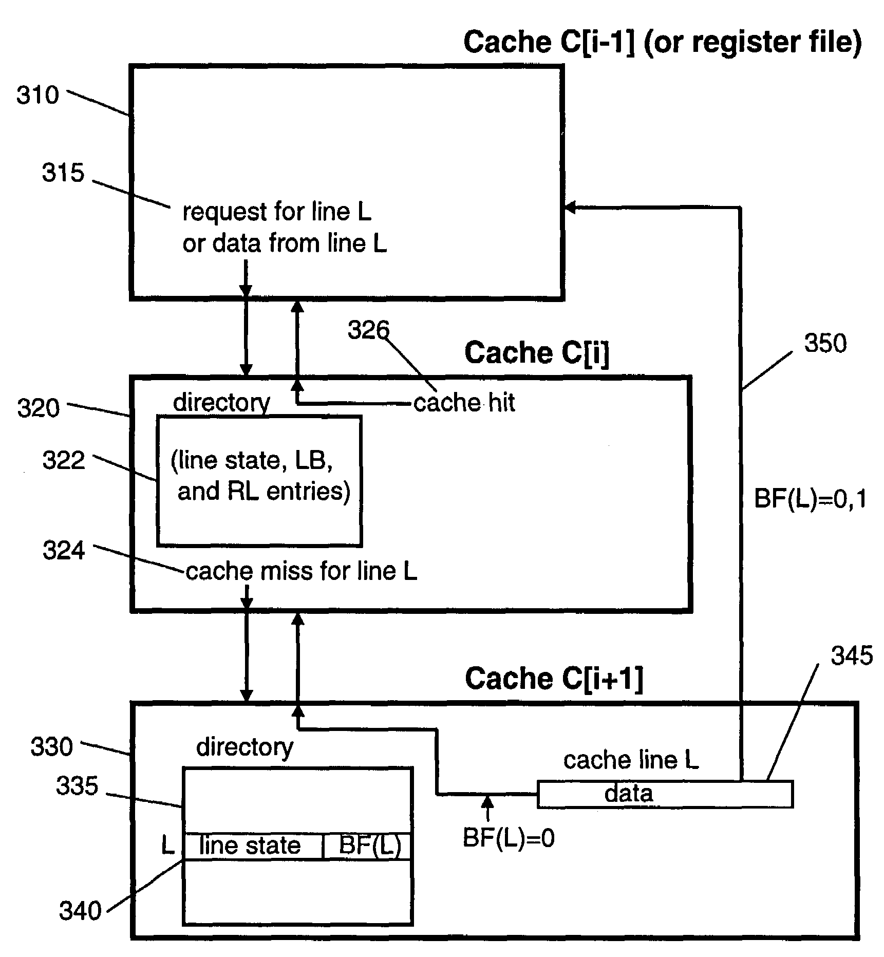
[0022]A first preferred embodiment will be described with respect to three caches at three levels in a cache hierarchy, C[i−1], C[i], and C[i+1], where it is understood that if i=1 then cache C[0] actually is made up of the processor registers.

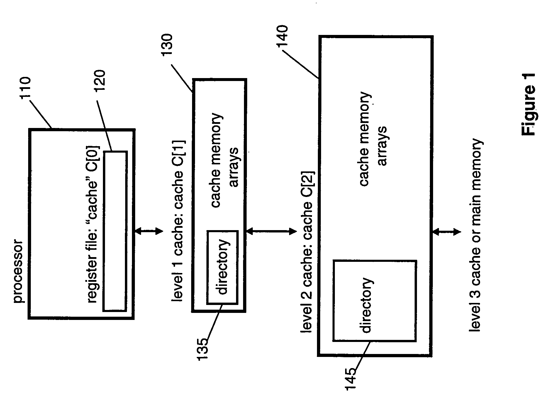
[0023]The case in which i=1 is illustrated in FIG. 1. In this example “cache” C[0]120 is made up of the processor register file. Cache bypass involves transferring data requested by an instruction issued by the processor 110 directly from the L2 (level 2) cache C[2]140 to the register or registers, bypassing the L1 (level 1) cache C[1]130. This takes place when, as determined by the L1 directory 135 and L2 directory 145, the cache line containing the requested data is resident in the L2 cache C[2]140 but not resident in the L1 cache C[2]130.

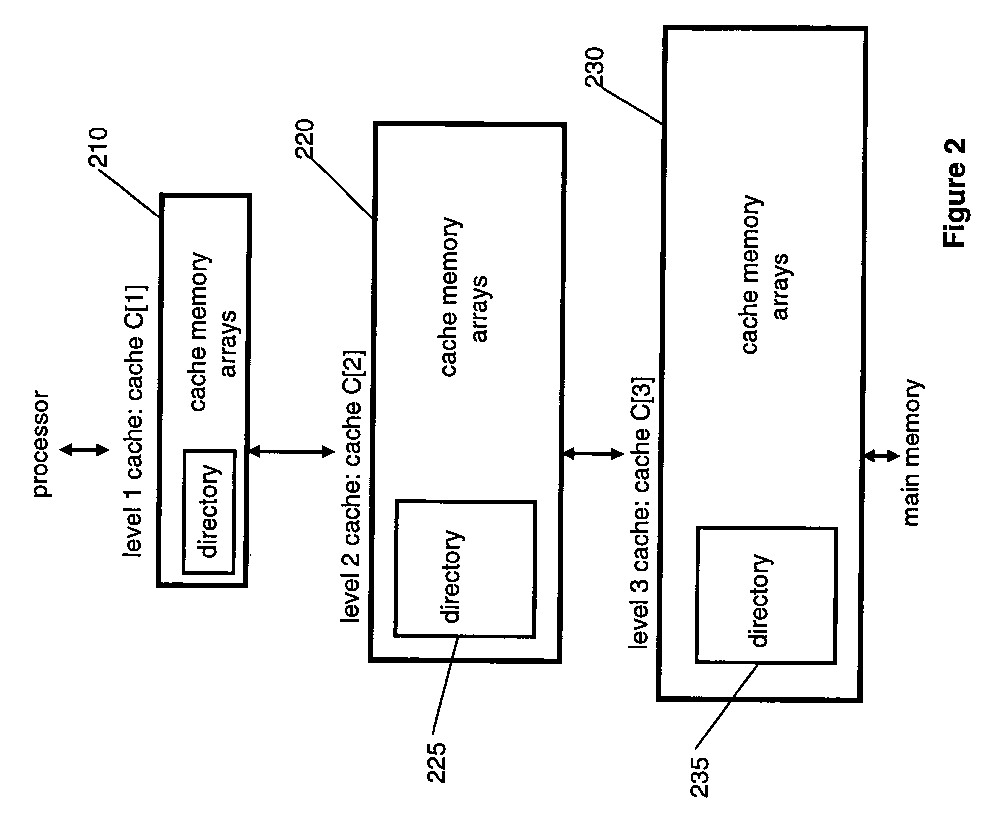
[0024]FIG. 2 illustrates the case in which i=2. In this example the cache hierarchy includes an L1 (level 1) cache C[1]210, an L2 (level 2) cache C[2]220, and an L3 (level 3) cache C[3]230. Cache bypass inv...


PUM


Abstract

Arrangements and method for enabling and disabling cache bypass in a computer system with a cache hierarchy. Cache bypass status is identified with respect to at least one cache line. A cache line identified as cache bypass enabled is transferred to one or more higher level caches of the cache hierarchy, whereby a next higher level cache in the cache hierarchy is bypassed, while a cache line identified as cache bypass disabled is transferred to one or more higher level caches of the cache hierarchy, whereby a next higher level cache in the cache hierarchy is not bypassed. Included is an arrangement for selectively enabling or disabling cache bypass with respect to at least one cache line based on historical cache access information.

Description

[0001]This invention was made with Government support under Contract No.: NBCH30390004 awarded by the Defense Advanced Research Projects Agency. The Government has certain rights in this invention.FIELD OF THE INVENTION[0002]The present invention generally relates to the design of multi-level cache architectures in computer systems, and more specifically to the design of such architectures in which cache lines residing in a lower level cache may bypass an intermediate cache in the cache hierarchy when the cache lines are requested by and stored in a higher level cache.BACKGROUND OF THE INVENTION[0003]One may begin by considering (for example) a computer system with a processor together with L1 (level 1) and L2 (level 2) caches. In the case of an L1 miss, it is clearly advantageous to bypass the L1 and load data from the L2 directly into processor registers in the case that the cache line, if it had been loaded into the L1, would never have been re-used before being replaced. In this...

Claims


Application Information

Patent Timeline
Patent Type & Authority Patents(United States)
IPC IPC(8): G06F12/00
CPCG06F12/0888G06F12/0897
Inventor HU, ZHIGANGROBINSON, JOHN T.SHEN, XIAOWEISINHAROY, BALARAM
Owner INT BUSINESS MASCH CORP
Why Eureka
Try Eureka