Heat dissipating system of high-speed circular knitting machine

Inactive Publication Date: 2006-05-02
PAI LUNG MACHINERY MILL CO LTD
View PDF7 Cites 8 Cited by
  • Summary
  • Abstract
  • Description
  • Claims
  • Application Information

AI Technical Summary

Benefits of technology

[0005]The primary objective of the present invention is to provide a heat dissipating system of a high-speed circular knitting machine that supply a low-temperature gas to the cylinder base and its p

Problems solved by technology

The high heat will affect the movement among components due to the thermal expansion, and also may cause a breaking of yarns and produce defective products since the yarns cannot bear the high heat.
However, the foregoing heat dissipating device use the air at room temperature for dissipating the heat, and thus it can only

Method used


Image

  • Heat dissipating system of high-speed circular knitting machine
  • Heat dissipating system of high-speed circular knitting machine
  • Heat dissipating system of high-speed circular knitting machine

Examples


Example

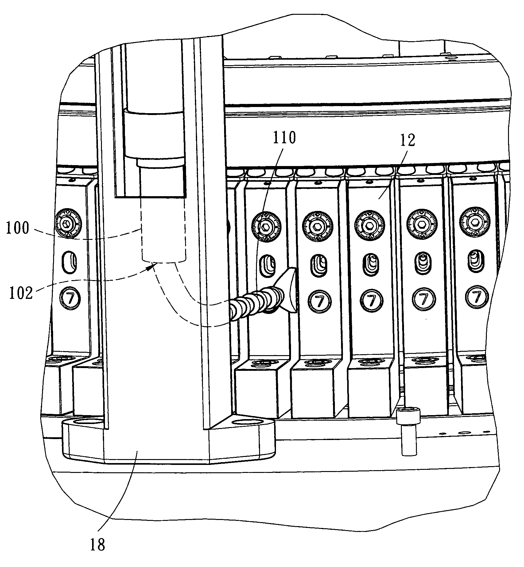
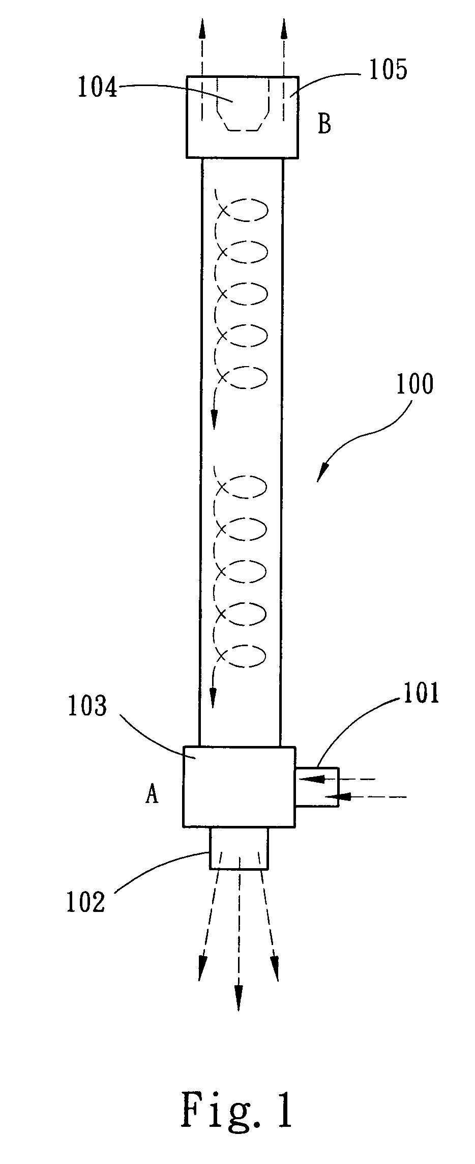
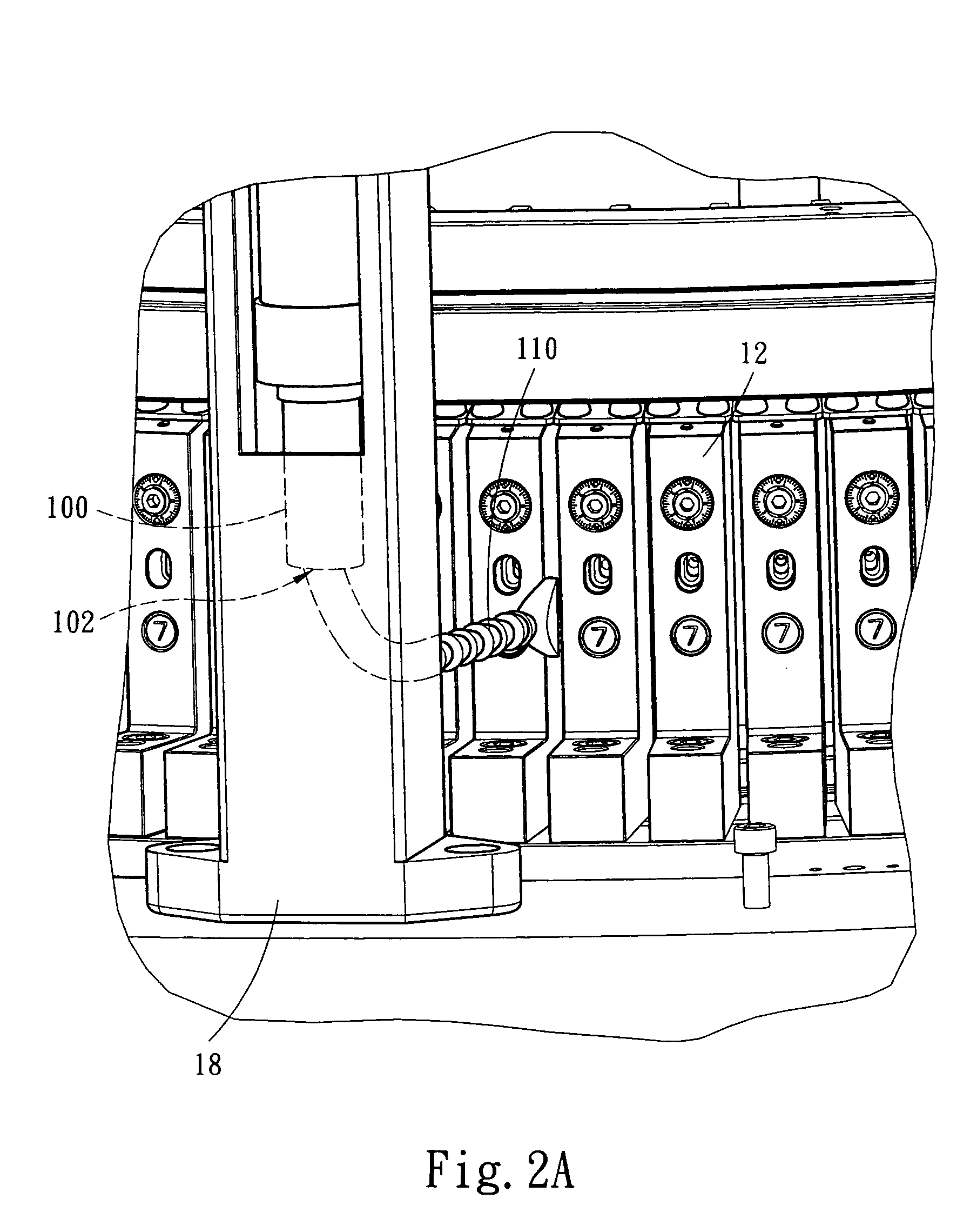
[0013]Refer to FIG. 1 for a heat dissipating system of a high-speed circular knitting machine in accordance with the present invention. The invention provides a super low temperature air gun 100 that requires no refrigerant or power, which is used extensively in the areas of cooling knives during the cutting and drilling metals, rapid cooling for soldering electronic components, and cooling plastic formation. The inventor of the present invention installs the super low temperature air gun 100 on the circular knitting machine 10 (as shown in the following figures) and aims a cold air outlet 102 of the super low temperature air gun 100 at the high-speed rotary cylindrical base 11 (which is a position of a high heat source produced in the knitting process) and blows cold air at the cylindrical base 11 of the circular knitting machine 10 to effectively lower the high heat of the cylinder base 11 and its peripheral components.

[0014]The structure and the cooling principle of the super low...


PUM


Abstract

A heat dissipating system of a high-speed circular knitting machine includes a super low temperature air gun. Cold air is ejected from a cold air outlet of the super low temperature air gun for carrying away the high heat produced by a cylinder base during a knitting process. The super low temperature air gun is connected to an extension pipe and extended to a gap between a cutting disc and a pressing plate, or saddle bases, or a lower rhombus ring and two saddle bases, or yarn feeding nozzles. Cold air ejected from the cold air outlet passes through the gap to the cylinder base or other peripheral components of the high-speed circular knitting machine to achieve the heat dissipating effect. The super low temperature air gun is installed inside a leg for supporting a yarn supplying device or on its external surface or on a yarn feeding ring.

Description

FIELD OF THE INVENTION[0001]The present invention relates to a heat dissipating system of a high-speed circular knitting machine, and more particularly to a heat dissipating system capable of effectively lowering the high heat produced by a circular knitting machine during a knitting process.BACKGROUND OF THE INVENTION[0002]In general, a circular knitting machine is composed of three sections which are a yarn supply section, a knitting section, and a cloth rolling section. The cylinder of the knitting section rotates about the center of the circular knitting machine, and a knitting needle is installed in a groove of the cylinder base and guided by a track of a cam to -displace up and down while the cylinder base is rotating. When the knitting needle displaces up and down in the groove of the cylinder base, the sinker is pushed out timely to carry out the knitting with the knitting needle. It is worth to note that the knitting needle will constantly rub with the groove of the cylinde...

Claims


Application Information

Patent Timeline
IPC IPC(8): D04B35/30
CPCD04B35/30
Inventor CHEN, SHIH-LUNG
Owner PAI LUNG MACHINERY MILL CO LTD
Why Eureka
Try Eureka