
Driving device, particularly lifting device for a working vehicle

Active Publication Date: 2006-05-02
DANFOSS PAUER SOLYUSHENS APS
View PDF10 Cites 7 Cited by
  • Summary
  • Abstract
  • Description
  • Claims
  • Application Information

AI Technical Summary

Benefits of technology

[0011]With this embodiment, the advantages of a single-acting drive, namely the simple operation, are combined with the additional advantages of a double-acting drive. With a double-acting drive, it is, for example, possible not only to use the lifting device for lifting an attachment, but also to press the lifting device downward, with or without a fixed attachment. With such a pressing, it is possible to lift the working vehicle on the side, on which the lifting device is arranged. When this is the tail, it is possible, by means of the lifting device, to lift the vehicle so much that the rear wheels can be changed, chains can be mounted or twin wheels can be mounted. To facilitate the understanding of the following, the word “lifting connection” is used for the first connection, and the word “lowering connection” is used for the second connection.
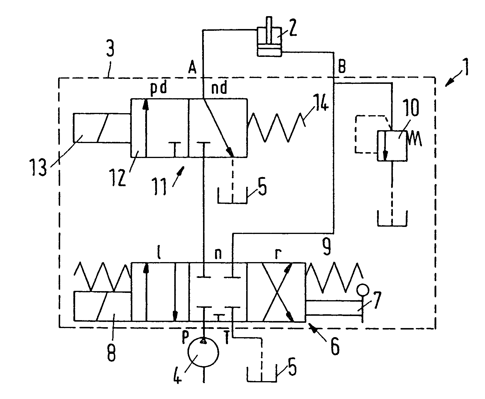
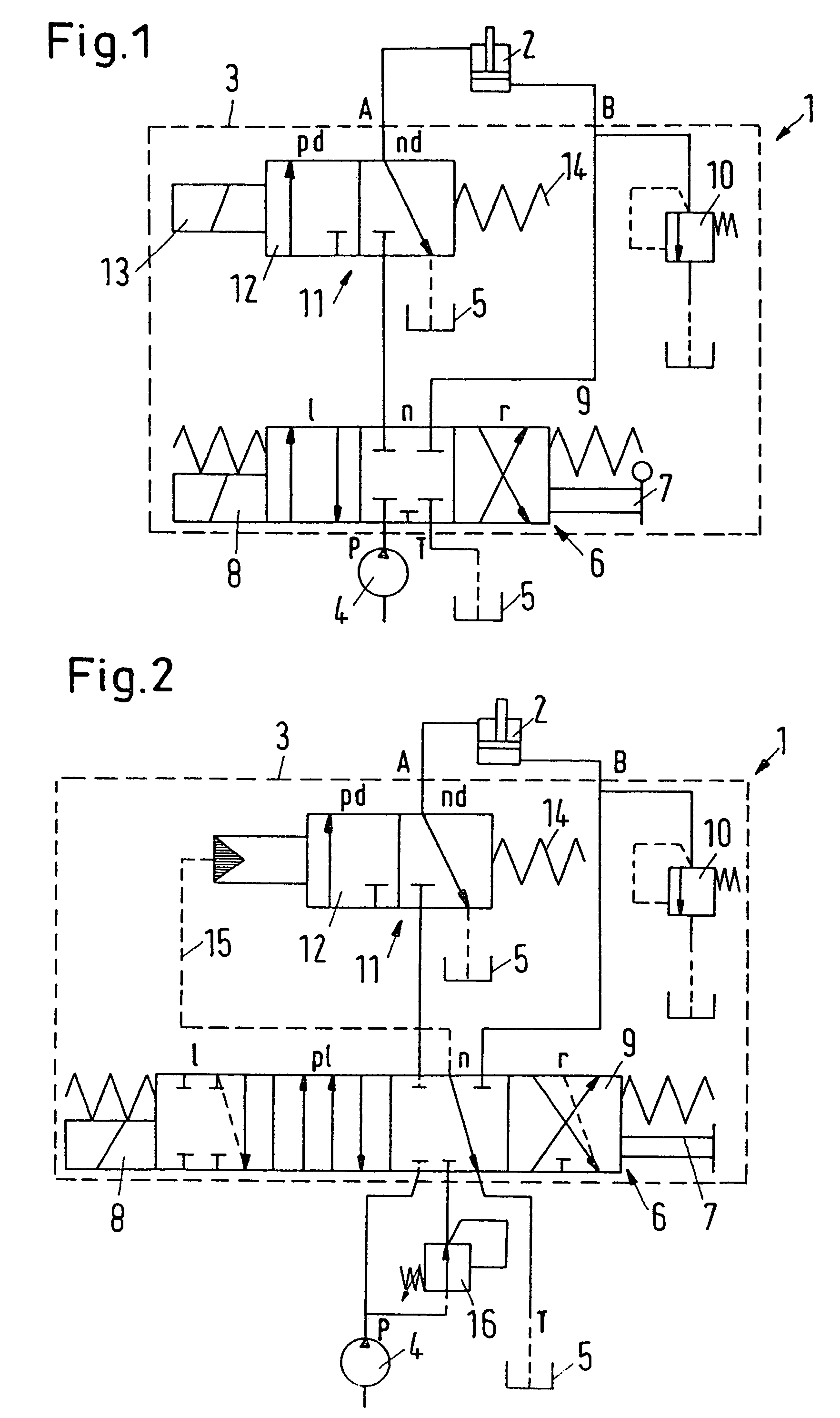
[0016]Preferably, the changeover valve is connected with the second connection of the motor. In order to facilitate the distinction between the connections of motor, the terms “lifting connection” and “lowering connection” were introduced above. The lifting connection, or the first connection, is the connection of the motor, which is supplied with pressurised hydraulic fluid, when the motor is to lift a load, for example an attachment. The lowering connection, or the second connection, is the connection of the motor, through which hydraulic fluid flows into the motor, when the load is lowered. During single-acting operation, this fluid is merely sucked from the tank. During double-acting operation, this fluid is then supplied under pressure by the pump. The supply of fluid from the pump to the lowering connection takes place via the changeover valve. When the changeover is connected directly with the lowering connection, the control is relatively simple.
[0018]Preferably, the control valve sets a double-acting function of the drive in an area, in which the lowering speed is in the lower end of the speed range of the drive. Thus, the double-acting function of the motor is chosen, when the lowering speed is low. This reduces the risk of damage caused by an unskilled or incorrect operation of the lifting device. In most of the cases, in which the double-acting function of the drive is required, a slow lowering speed is desired anyway, for example when lifting the vehicle.
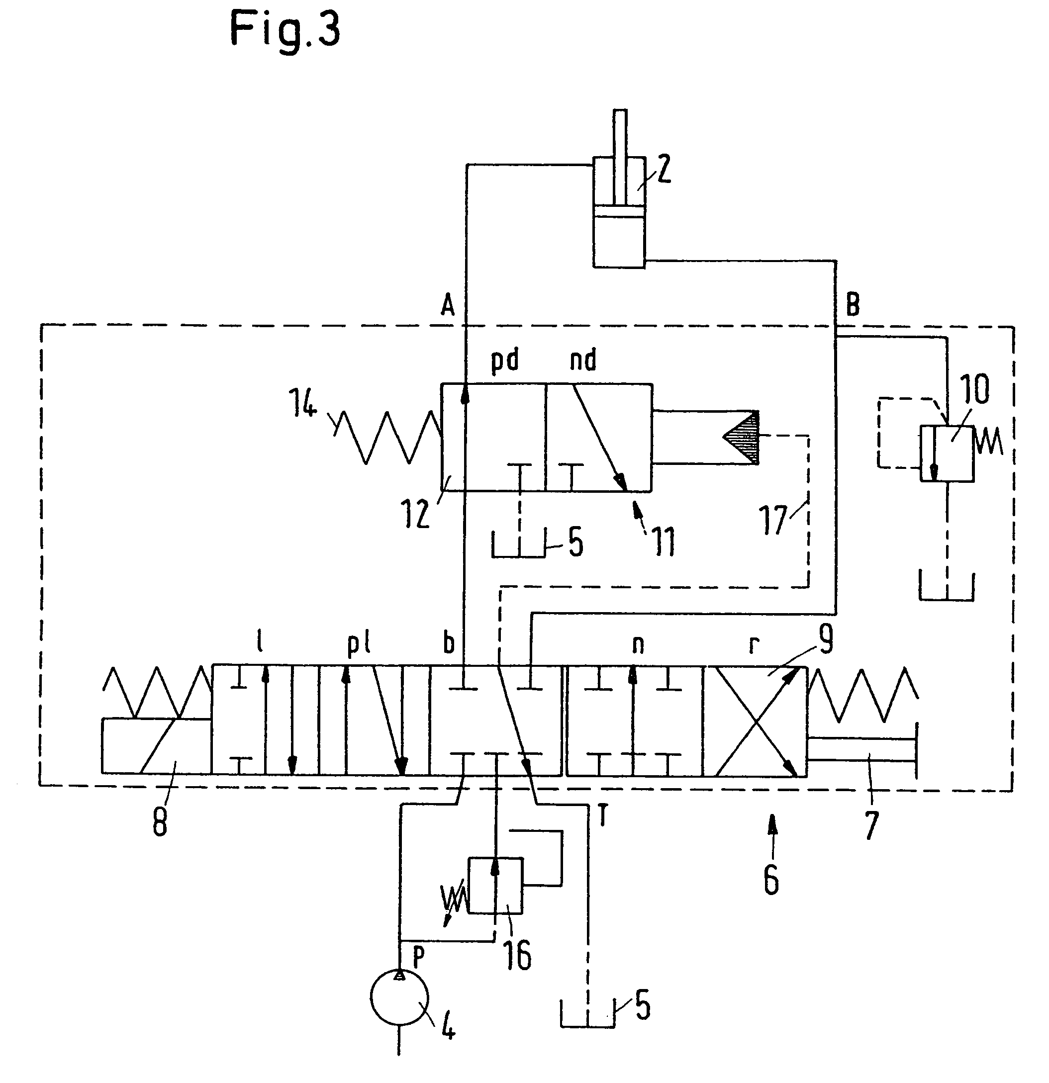
[0019]Preferably, the control valve has a locking position, in which the changeover valve is locked in a position, in which the connection of the motor connected with the changeover valve is closed. With such a locking position, the lifting device can be locked in any assumed position. This is particularly expedient, when, by means of the lifting device, the vehicle has been lifted and the user intends to perform assembly work. When the user has previously switched the control valve to the locked position, he can work on the vehicle without having to fear that the vehicle is lowered in an uncontrolled manner.
[0021]Preferably, a controllable non-return valve is located between the pump and the first connection, which non-return valve can be opened by a pressure in front of the changeover valve. This embodiment permits a controlled lowering of a load located on the lifting device. When the change-over valve is in a position, in which the drive is single-acting, the pressure from the pump can only get as far as the change-over valve anyway, where it builds up the pressure required for opening the non-return valve. When, however, the changeover valve has been switched to the double-acting position, the pressure from the pump can get through the changeover valve. However, the pressure in front of the changeover valve will increase anyway, as firstly, the non-return valve prevents the discharge of fluid from the motor. Not until the lowering pressure in the motor has increased to a predetermined value, the pressure in front of the changeover valve gets so high that it is sufficient for opening the non-return valve.

Problems solved by technology

In practice, double-acting drives are barely found on such lifting devices.

Method used


Image

  • Driving device, particularly lifting device for a working vehicle
  • Driving device, particularly lifting device for a working vehicle
  • Driving device, particularly lifting device for a working vehicle

Examples


Embodiment Construction

[0028]FIG. 1 shows a lifting device on a vehicle, not shown in detail, with a hydraulic motor 2 in the form of a hydraulic cylinder. The motor 2 is connected with a control valve arrangement 3, which has a pump connection P, which is connected with a pump 4 and a tank connection T, which is connected with a tank 5. The control valve arrangement 3 has a lowering connection A and a lifting connection B. The lifting connection B is the connection, through which the motor 2 is supplied with hydraulic fluid, when the motor 2 is lifting a load, not shown in detail. The lowering connection A is the connection, through which the motor 2 is supplied with hydraulic fluid, when the load is lowered. As will be explained in the following, the supply of hydraulic fluid via the lowering connection can take place in two different ways.

[0029]In a manner known per se, the control valve arrangement 3 has a control valve 6, which can be activated by means of a handle 7 or an electromagnet 8. The contro...


PUM


Abstract

The invention concerns a driving device, particularly a lifting device for a working vehicle, with a drive in the form of a hydraulic motor, the drive having a first connection and a second connection, a pump and a control valve arrangement between the drive and the pump. It is endeavoured to provide a simple way of extending the functionality of such lifting devices. For this purpose, the control valve arrangement can be switched from a first operating state, in which the motor is driven in a single-acting manner, to a second operating state, in which the motor is driven in a double-acting manner.

Description

CROSS-REFERENCE TO RELATED APPLICATIONS[0001]This application is entitled to the benefit of and incorporates by reference essential subject matter disclosed in German Patent Application No. 103 10 314.7 filed on Mar. 10, 2003.FIELD OF THE INVENTION[0002]The invention concerns a driving device, particularly a lifting device for a working vehicle, with a drive in the form of a hydraulic motor, said drive having a lifting connection and a lowering connection, a pump and a control valve arrangement between the drive and the pump.BACKGROUND OF THE INVENTION[0003]Such a driving device in the form of a lifting device is known from, for example, DE 35 22 823 A1.[0004]In the following, the invention will be described on the basis of a tractor, the lifting device being formed by the so-called toolbar (hitch). Attachments are fixed to the toolbar, for example, a plough, a harrow or a mowing tool. By means of the drive, the attachments can then be brought to the right working height, so that, f...

Claims


Application Information

Patent Timeline
IPC IPC(8): F15B11/08A01B63/10
CPCA01B63/1013F15B11/08F15B2211/30565F15B2211/3122F15B2211/31529F15B2211/7053F15B2211/329F15B2211/355F15B2211/50518F15B2211/5159F15B2211/55F15B2211/31558
Inventor JOERGENSEN, MARTIN RAADKJAER
Owner DANFOSS PAUER SOLYUSHENS APS
Learn More