Distributor device for use in metal casting

a distributor device and metal casting technology, applied in the direction of blast furnace components, blast furnace types, blast furnace types, etc., can solve the problems of reducing the rigidity of the distributor, dimensional accuracy of the distributor is difficult to measure and control within normal engineering tolerances, and the use of the distributor adds significantly to the cost of the manufacturing process

Inactive Publication Date: 2006-05-02
PYROTEK ENG MATERIALS
View PDF26 Cites 3 Cited by
  • Summary
  • Abstract
  • Description
  • Claims
  • Application Information

AI Technical Summary

Benefits of technology

[0013]It is an object of the present invention to provide a distributor device that mitigates at least some of the problems of the aforementioned distributor devices.

Problems solved by technology

If the flow is turbulent, impurities can be introduced into the aluminium, which can cause serious problems during subsequent manufacturing processes.
However, because these devices are constructed largely by hand, they are relatively expensive and their use therefore adds significantly to the cost of the manufacturing process.
This means that the positioning and shape of the device can be inconsistent, and the dimensional accuracy of the device is difficult to measure and control within normal engineering tolerances.
Furthermore, the coatings on the woven glass fibre weaken at metal casting temperatures, leading to reduced rigidity of the distributor.
These factors combine to limit the reliability of metal distribution, and this leads to inconsistencies in the casting operation.
Further, fibres can occasionally come loose from the fabric of the distributor and become entrained in the molten aluminium, thereby introducing impurities into the aluminium ingot and potentially causing considerable difficulties in subsequent manufacturing processes.
Further, conventional distributors do not drain well after use and are sometimes provided with additional drain apertures in the bottom wall of the outer shell to ensure complete drainage.
However, aluminium can also flow through these apertures during casting, thereby disturbing the desired liquid metal flow pattern.
The bag is flexible and is susceptible to the disadvantages mentioned above.
One of these is a flexible bag type, which is susceptible to the disadvantages mentioned above.
The nozzle is geometrically complex and is difficult and expensive to produce.

Method used


Image

  • Distributor device for use in metal casting
  • Distributor device for use in metal casting
  • Distributor device for use in metal casting

Examples


Embodiment Construction

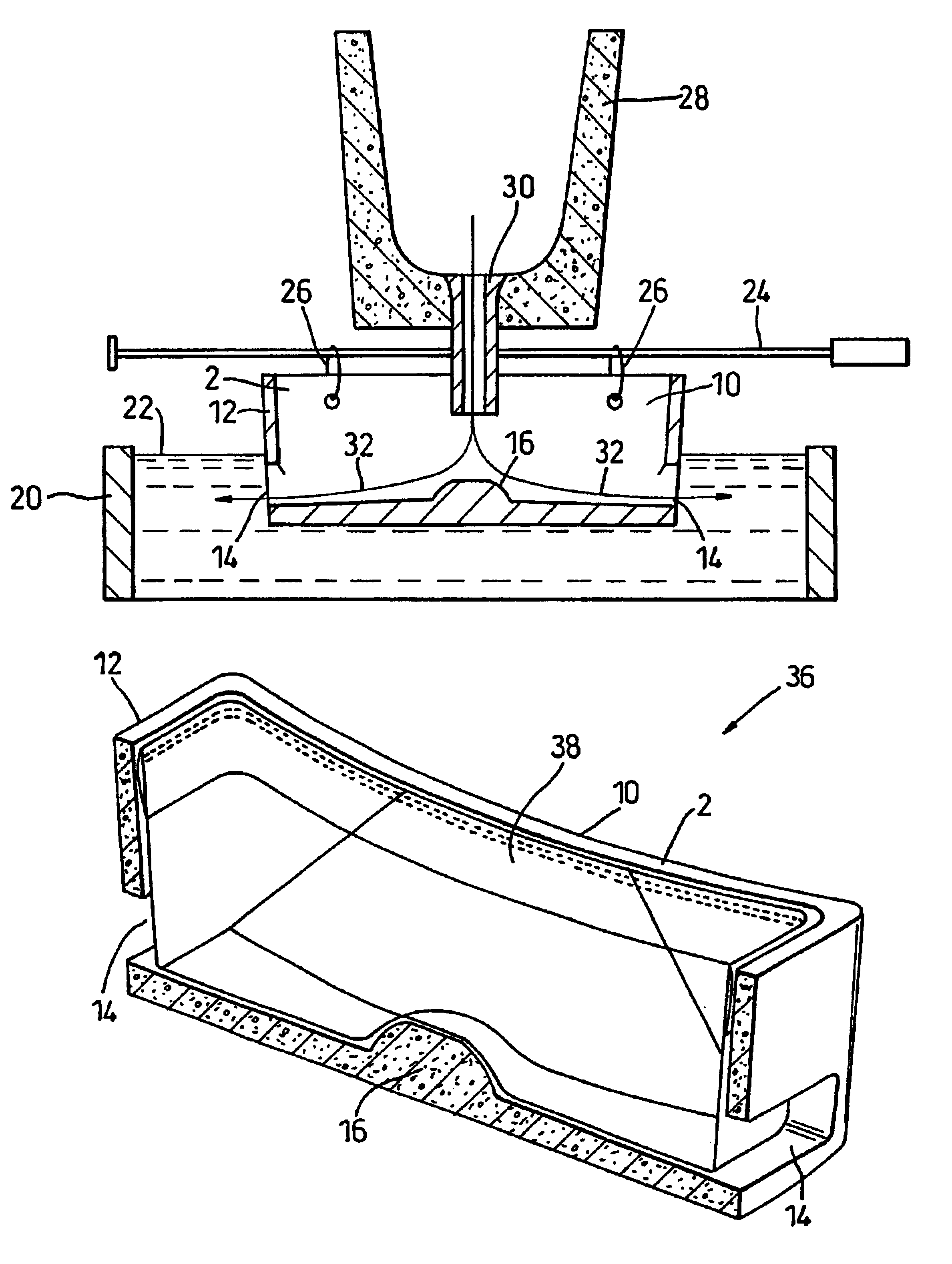
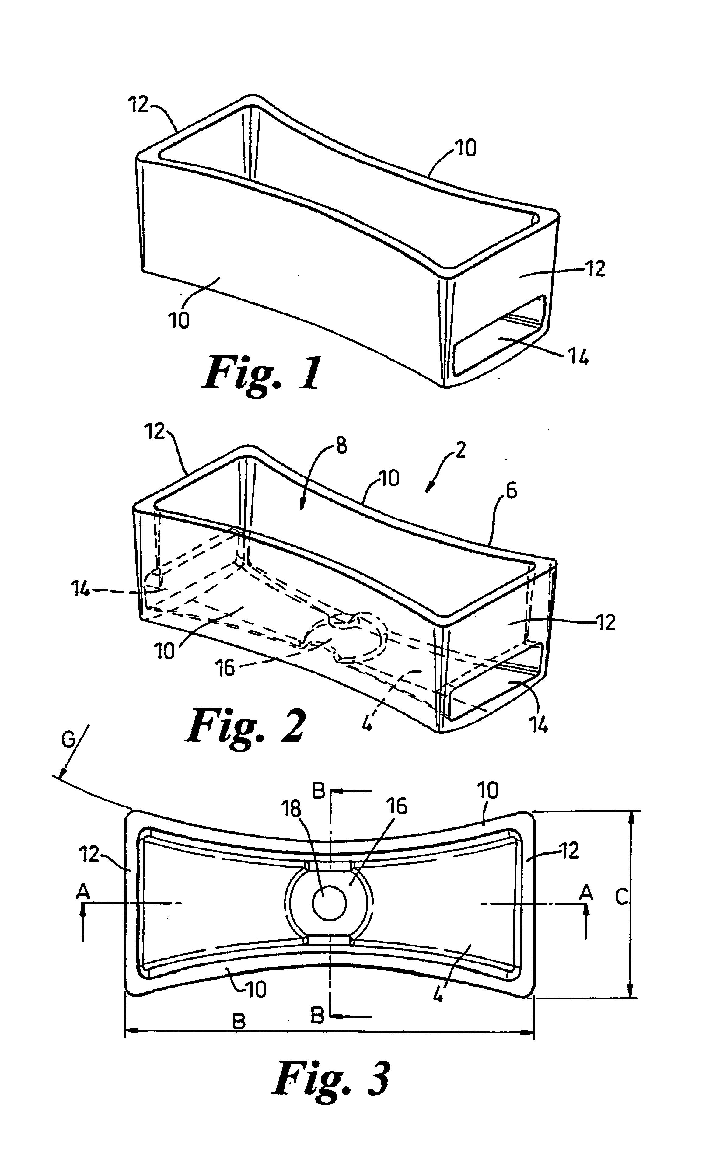
[0048]A distributor device 2 according to a first embodiment of the invention is shown in FIGS. 1 to 5 of the drawings. The device is intended for use in an aluminium casting operation to direct the flow of molten aluminium into a mould, the device being located in use just above the mould, so that during pouring it is partially submerged below the surface of the molten metal in the mould.

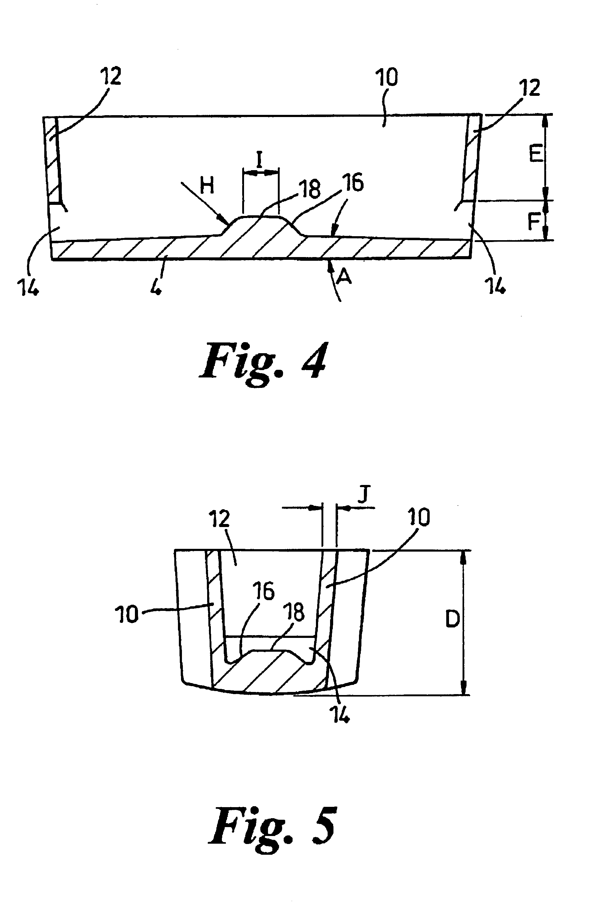
[0049]The distributor device 2 includes a rigid, substantially bowl-shaped receptacle of a refractory material having a base member 4 and a peripheral wall 6 that extends upwards from the base and is inclined slightly outwards, forming an inlet opening 8 towards the upper end of the device. The peripheral wall 6 is four-sided and includes two side wall members 10 and two end wall members 12. The side wall members 10 are curved inwards lending the device a bi-concave shape, the separation of the side wall members increasing towards the ends of those walls.

[0050]An outlet opening 14 is provided in th...


PUM

PropertyMeasurementUnit
temperatureaaaaaaaaaa
flexibleaaaaaaaaaa
temperaturesaaaaaaaaaa

Abstract

A distributor device for use in aluminium casting includes a rigid, substantially bowl-shaped receptacle (2) of a refractory material having a base member (4) and a peripheral wall (6) that extends upwards from the base. The receptacle has an inlet opening (8) towards the upper end thereof and a pair of outlet openings (14) towards the base thereof. The device is constructed and arranged such that, in use, molten aluminium poured into the distributor device through the inlet opening (8) is redirected by the distributor device and flows outwards into the mould through the outlet openings (14).

Description

CROSS-REFERENCE TO RELATED APPLICATION[0001]This application is a 371 of PCT / GB00 / 08951 filed on Aug. 4, 2000.BACKGROUND OF THE INVENTION[0002]The invention relates to a distributor device for use in an aluminium casting operation.[0003]In the process for manufacturing aluminium, after completion of the refining process, the molten aluminium is cast into ingots or billets that are subsequently used in processes for manufacturing aluminium products, for example aluminium foil.[0004]During the casting operation, the molten aluminium is transferred from a holding furnace into a water-cooled mould above a casting pit, where it solidifies to form an aluminium ingot.[0005]It is important that the flow of aluminium into the mould is smooth and non-turbulent, so that the solidification and temperature profile of the metal can be carefully controlled. If the flow is turbulent, impurities can be introduced into the aluminium, which can cause serious problems during subsequent manufacturing pr...

Claims


Application Information

Patent Timeline
Patent Type & Authority Patents(United States)
IPC IPC(8): B22D37/00B22C9/08B22D7/12B22D11/00B22D11/049B22D11/103B22D11/119B22D21/04B22D35/04B22D35/06B22D41/00B22D41/50B22D43/00C22B21/00
CPCB22C9/082B22D7/12B22D11/103C22B21/0084B22D35/04B22D41/003B22D41/50B22D11/119
Inventor VINCENT, MARKTREMBLAY, SYLVAIN
Owner PYROTEK ENG MATERIALS
Why Eureka
Try Eureka