
Controlling a pressure transient in a well

Inactive Publication Date: 2006-05-02
SCHLUMBERGER TECH CORP
View PDF16 Cites 44 Cited by
  • Summary
  • Abstract
  • Description
  • Claims
  • Application Information

AI Technical Summary

Benefits of technology

[0012]Accordingly, a system for controlling a pressure transient is provided that facilitates enhancing the fluid communication between a wellbore and an adjacent formation. The dynamic pressure control system comprises: perforating a wellbore by detonating a perforating tool, and filling at least a portion of the wellbore with a wellbore fluid selected for controlling the dynamic pressure transient upon and after detonation of the perforating tool.
[0013]The present inventive system facilitates controlling the dynamic pressure changes between the wellbore and the formation during perforations operations. Control of the dynamic pressure transient reduces the damage that may be incurred in prior art perforation operations. The inventive system may further include elements in the wellbore fluid to further enhance fluid communication.

Problems solved by technology

The process may also generate a tunnel full of rock debris mixed in with the perforator charge debris.
The shock damaged region and loose debris in the perforation tunnels may impair the productivity of production wells or the injectivity of injector wells.
One popular method of obtaining clean perforations is underbalanced perforating.
However, underbalance perforating may not always be effective and may be expensive and unsafe to implement in certain downhole conditions.
For example, when reservoir pressure is high and the formation matrix is weak this underbalanced pressure differential may result in collapse of the perforation tunnel and / or excessive sand production.
Prior art perforation operations often result in damage to the formation which has to be remedied to proceed with production or injection operations.
This damage is often caused by utilization of a fluid that allows an excessive dynamic pressure imbalance between the formation and the wellbore proximate the firing of the perforating gun.
When a hydrocarbon bearing reservoir is perforated with shaped charges, several events may occur to cause damage to the formation and impair productivity.
During an overbalanced state well fluid may enter the tunnels and deposit additional debris.
This debris is often difficult to remove from the perforation tunnels with the prior art wellbore fluids.
The perforation tunnels created may collapse due to dynamic pressure changes during the perforation process defeating the process or decreasing formation-wellbore communication.
Additionally, when the gun is fired with conventional fluids the rapid changes in the wellbore pressure results in “gun jumping.” This lead to damage to the downhole tools, perforating gun, and packers.

Method used


Image

  • Controlling a pressure transient in a well
  • Controlling a pressure transient in a well
  • Controlling a pressure transient in a well

Examples


Embodiment Construction

[0021]Refer now to the drawings wherein depicted elements are not necessarily shown to scale and wherein like or similar elements are designated by the same reference numeral through the several views.

[0022]As used herein, the terms “up” and “down”; “upper” and “lower”; and other like terms indicating relative positions to a given point or element are utilized to more clearly describe some elements of the embodiments of the invention. Commonly, these terms relate to a reference point as the surface from which drilling operations are initiated as being the top point and the total depth of the well being the lowest point.

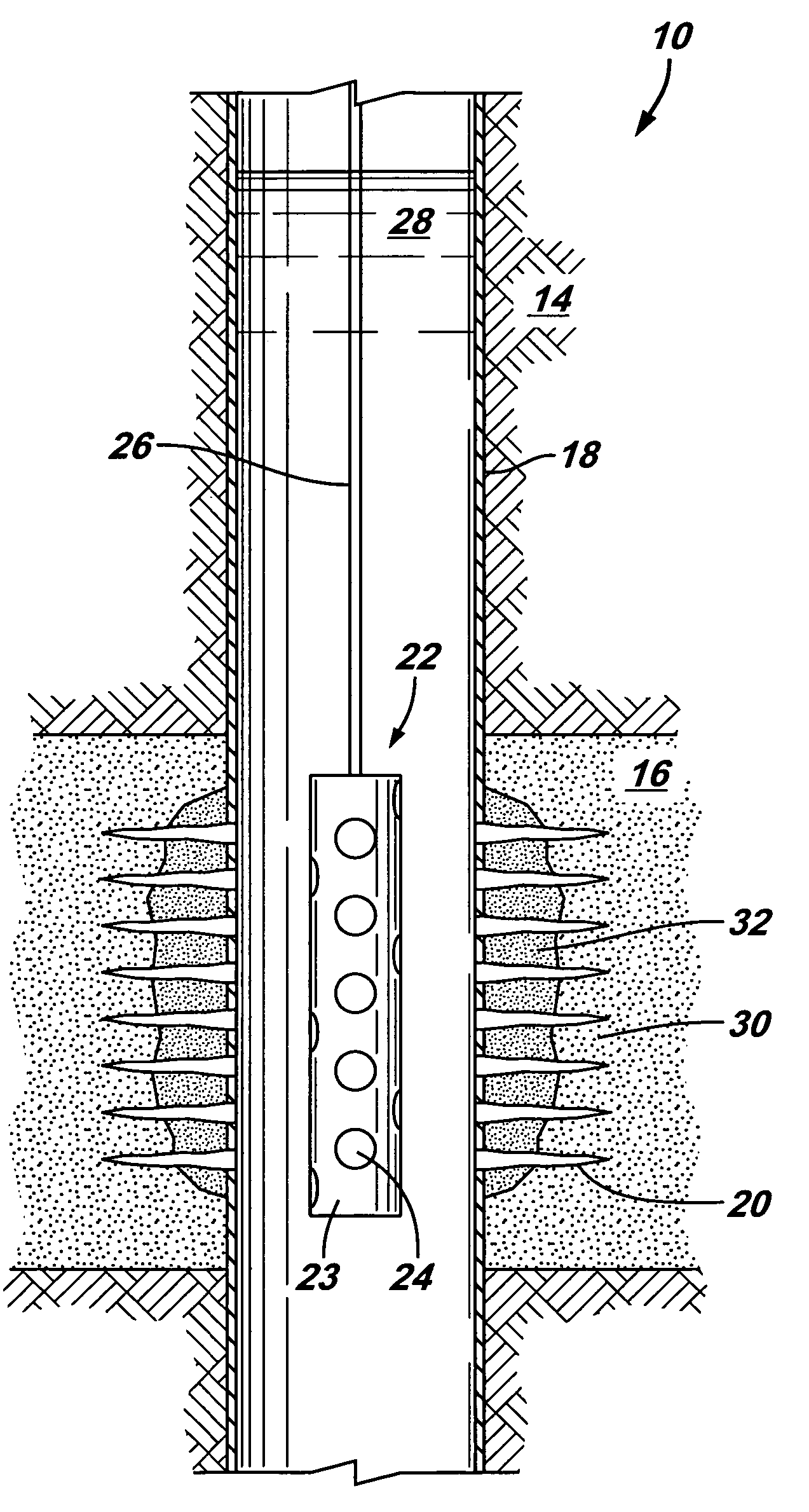
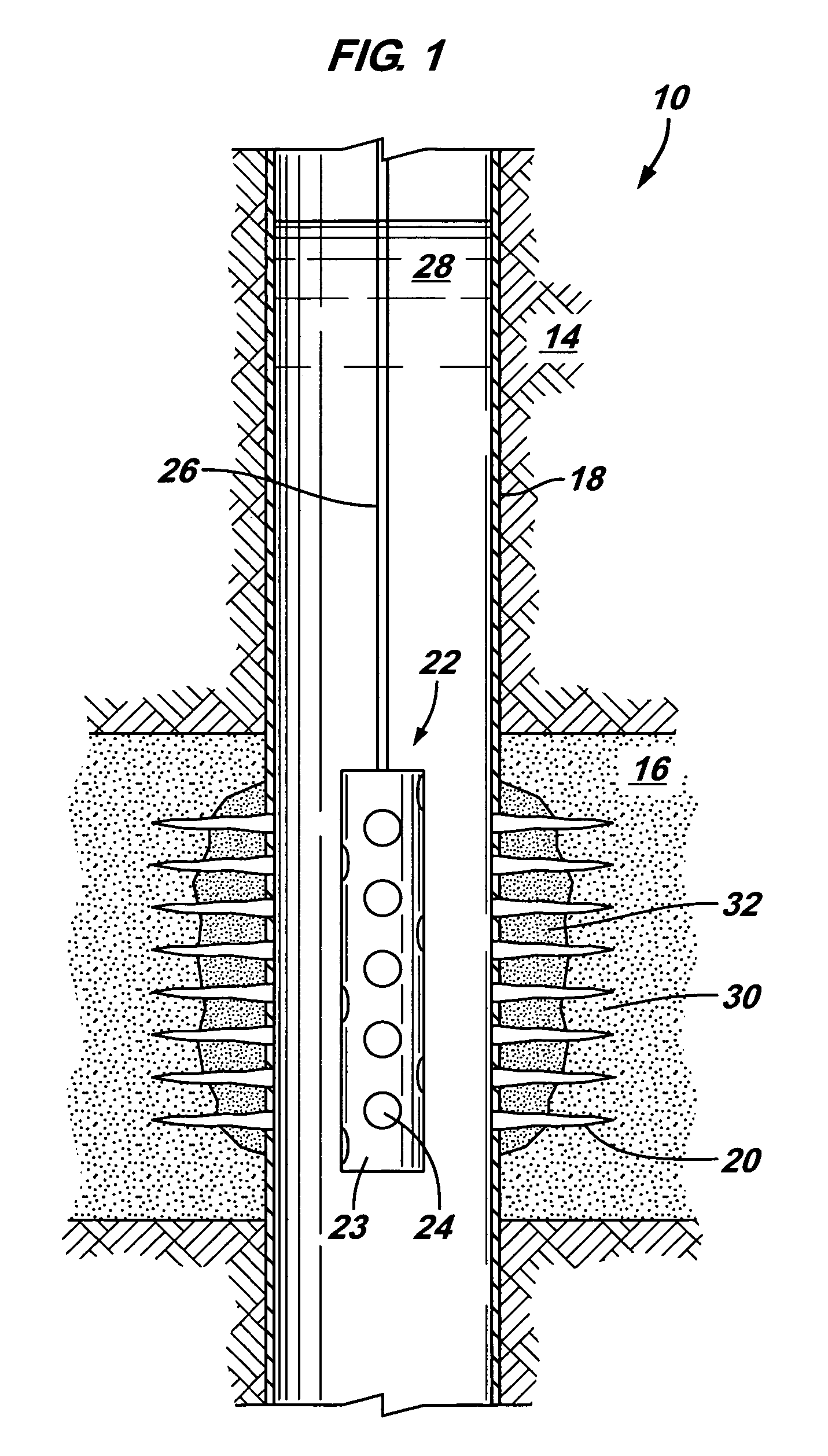
[0023]FIG. 1 is a schematic drawing of a perforating system of the present invention, generally designated by the numeral 10. Perforating system 10 includes a wellbore 12 that is drilled into the earth 14 to a desired formation 16 for producing a fluid from or injecting a fluid therein. Wellbore 12 often includes a casing 18, although wellbore 12 may be open at format...


PUM


Abstract

A system for controlling a dynamic pressure transient in a well during operations to provide fluid communication between the wellbore and adjacent formation. A method includes determining the characteristics of an adjacent formation, selecting a perforating tool for increasing fluid communication, determining a dynamic pressure transient to enhance the quality of the fluid communication and prevent damage, selecting a wellbore fluid to achieve the desired pressure transient, and performing the fluid communication process based on the selected parameters.

Description

RELATED APPLICATIONS[0001]This is a continuation-in-part, and claims the benefit of priority, of U.S. Ser. No. 10 / 667,011 entitled IMPROVING RESERVOIR COMMUNICATION BY CREATING A LOCAL UNDERBALANCE AND USING TREATMENT FLUID, filed on Sep. 19, 2003, which is a continuation-in-part of U.S. Ser. No. 10 / 316,614, filed Dec. 11, 2002, now U.S. Pat. No. 6,732,798, which is a continuation-in-part of U.S. Ser. No. 09 / 797,209, filed Mar. 1, 2001, now U.S. Pat. No. 6,598,682, which claims the benefit of U.S. Provisional Application Ser. Nos. 60 / 186,500, filed Mar. 2, 2000; 60 / 187,900, filed Mar. 8, 2000; and 60 / 252,754, filed Nov. 22, 2000. Each of the referenced applications are hereby incorporated by reference.FIELD OF THE INVENTION[0002]The present invention relates in general to improving fluid communication between a reservoir formation and a wellbore and more specifically to controlling a pressure transient during perforating operations.BACKGROUND[0003]To complete a well, one or more for...

Claims


Application Information

Patent Timeline
IPC IPC(8): E21B43/25E21B21/00E21B34/00E21B37/08E21B43/04E21B43/11E21B43/119E21B43/26E21B49/08
CPCF42D5/045E21B37/00E21B37/08E21B43/04E21B43/11E21B43/117E21B43/119E21B43/1195E21B43/26E21B49/08E21B49/087F42B3/02E21B21/00C09K2208/30E21B2021/006E21B2034/002E21B21/085E21B2200/04
Inventor WALTON, IANCHANG, FRANK F.
Owner SCHLUMBERGER TECH CORP
Features
  • Generate Ideas
  • Intellectual Property
  • Life Sciences
  • Materials
  • Tech Scout
  • Unparalleled Data Quality
  • Higher Quality Content
  • 60% Fewer Hallucinations
Learn More