Directly controlled proportional pressure limiting valve

a proportional control, pressure limiting valve technology, applied in the direction of fluid pressure control, pipe elements, instruments, etc., can solve the problem that the pressure limiting valve cannot reliably close any more, and achieve the effect of preventing damage to the valve seat, high precision, and reliable closur

Active Publication Date: 2006-05-02
BOSCH REXROTH AG
View PDF11 Cites 30 Cited by
  • Summary
  • Abstract
  • Description
  • Claims
  • Application Information

AI Technical Summary

Benefits of technology

[0005]It was, however, found that these variants having a valve body mounted with a play in the armature must also be m

Problems solved by technology

It is a problem in this solution that in a case of axial offset between the valve seat and the

Method used


Image

  • Directly controlled proportional pressure limiting valve
  • Directly controlled proportional pressure limiting valve
  • Directly controlled proportional pressure limiting valve

Examples


Embodiment Construction

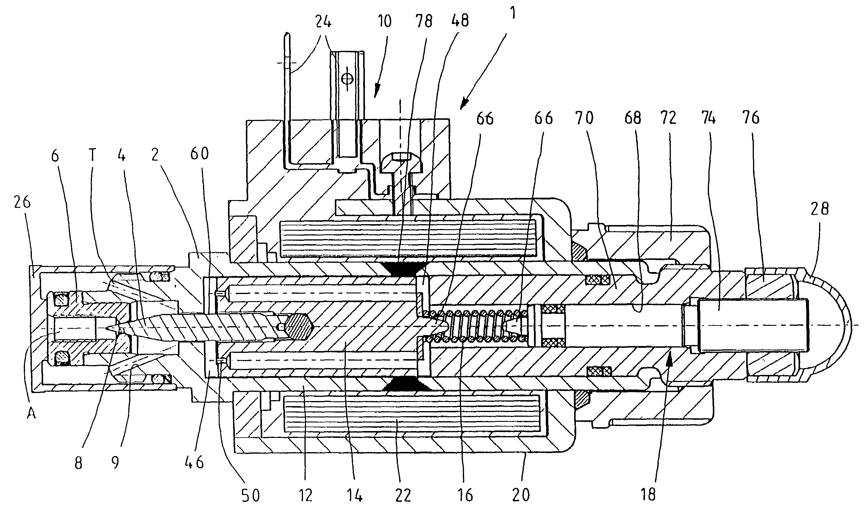
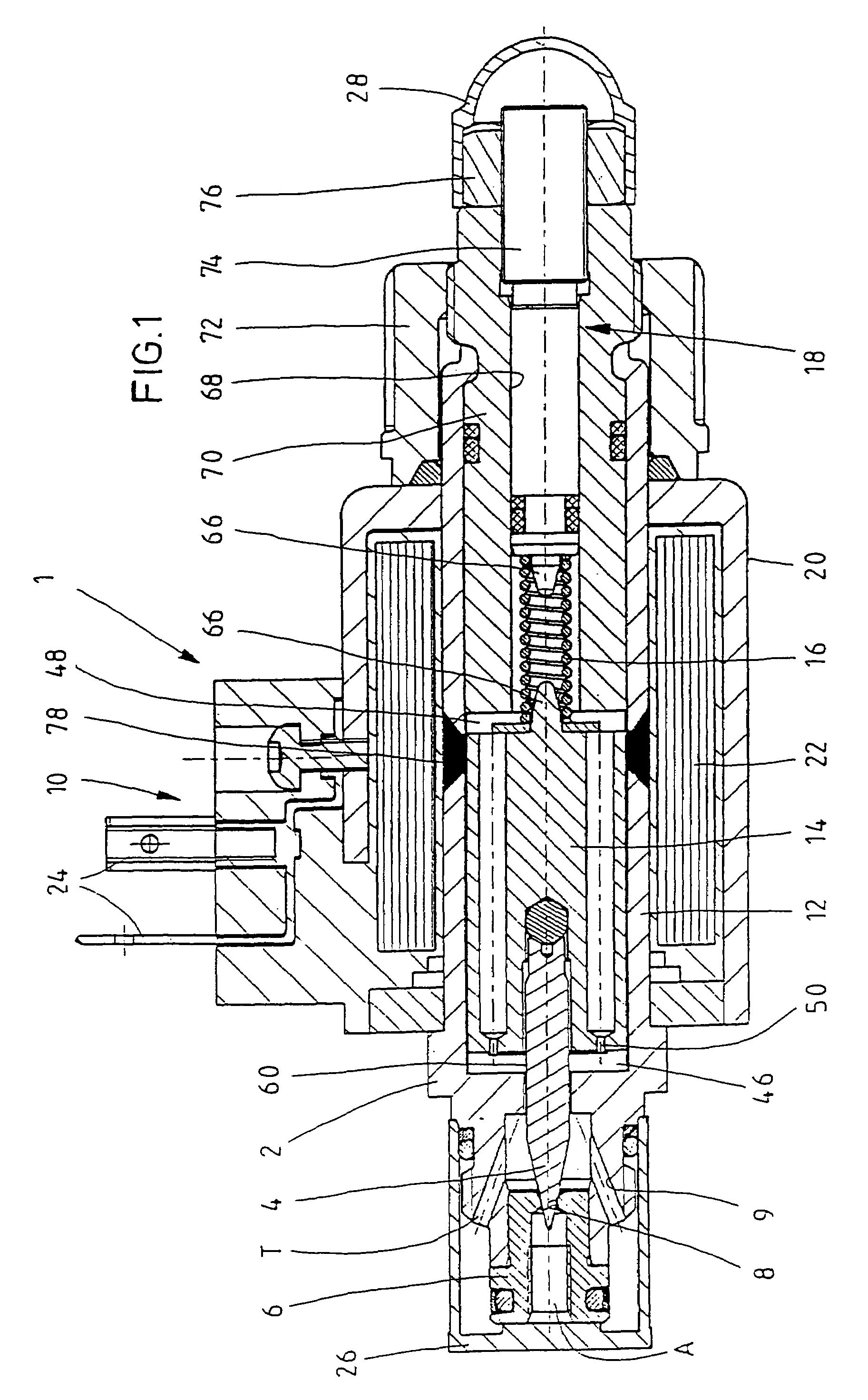
[0023]In accordance with the longitudinal sectional view represented in FIG. 1, the pressure limiting valve 1 has a valve housing 2 wherein a valve cone 4 is guided so as to be axially displaceable. Into the valve housing 2 a seat body 6 is inserted whereby an axial port A and a valve seat 8 are formed. This seat body 6 may be inserted in the housing by press-fitting, for example. In the valve housing 2 a radial drain or tank port T is formed by a group of oblique bores 9. Actuation of the valve cone 4 takes place with the aid of a proportional solenoid 10 axially mounted on the valve housing 2. The proportional solenoid 10 has a pole tube 12 realized integrally with the valve housing 2, in which an armature 14 is mounted. On the latter the valve cone 8 is supported. The armature 14 is biased in the closing direction of the valve cone 8 through the intermediary of a regulating spring 16. The bias of the regulating spring 16 may be varied by an actuating means 18. The proportional so...


PUM


Abstract

A proportionally adjustable pressure limiting valve wherein a valve cone may be actuated via an armature of a proportional solenoid. The valve cone is cardanically supported in the armature. Additional guidance of the valve cone is effected through the intermediary of a housing-side guide, wherein the play between valve cone and housing-side guide is designed to be less than the play between valve cone and armature.

Description

BACKGROUND OF THE INVENTION[0001]The invention relates to a directly controlled and proportionally adjustable pressure limiting valve achieved by the below described embodiments.[0002]The like pressure limiting valves are employed, e.g., as proportionally adjustable pressure limiting valves. In WO 00 / 50794 A1 a directly controlled pressure limiting valve is disclosed where an armature of a proportional solenoid acts on a valve cone through the intermediary of a tappet. The valve cone is slidingly guided in the valve housing, while the tappet contacting the valve cone is supported in the armature and extends through a guide disc of the valve housing. It is a problem in this solution that in a case of axial offset between the valve seat and the valve cone there is a possibility of the pressure limiting valve not reliably closing any more.[0003]In DE 196 25 349 a solution improved in this respect is proposed, wherein the valve cone is supported directly in the armature. To this end, th...

Claims


Application Information

Patent Timeline
IPC IPC(8): F16K31/02F16K31/06G05D16/20
CPCG05D16/2013F16K31/0693G05D16/2022
Inventor SCHNEIDER, KONRADMULLER, THOMAS
Owner BOSCH REXROTH AG
Why Eureka
Try Eureka