Methods and apparatus for controlling airflow in a fiber extrusion system

a fiber extrusion and airflow technology, applied in the direction of dough shaping, manufacturing tools, food shaping, etc., can solve the problems of entrapped air within the room, substantial filament and fabric disturbance, and remains a serious problem, so as to minimize the criticality of the open area, reduce the suction effect, and maximize the capability of multi-laydown

Active Publication Date: 2006-05-02
HILLS CO
View PDF8 Cites 6 Cited by
  • Summary
  • Abstract
  • Description
  • Claims
  • Application Information

AI Technical Summary

Benefits of technology

[0014]By reducing the amount of entrained air in the fiber extrusion process, the airflow control device of the present invention can substantially reduce the suction typically required through the web-forming surface, which minimizes the criticality of the open area of the expensive forming wire while maximizing the capability of multi-laydowns, and the capability to make composites, even composites onto impervious or microporous substrates. Likewise, the device may reduce the energy costs required because of lower air handling and conditioning requirements, and the air can be recycled if economical. The airflow control device also considerably reduces the noise caused by open airflow.
[0015]The airflow control device also provides the versatility to control filament velocity in web formation independent of a filament spinning velocity. In general, improved web formation can be achieved, particularly at higher spinning speeds, due to reduced air disturbance and a smoother laydown of fibers onto the foraminous surface, and improved fiber orientation can be obtained.

Problems solved by technology

The problem of handling the large volume of compressed air, quench air and room air induced into the aspirator, and the entrained air from within the room below the aspirator, has been and remains a serious problem despite nearly fifty years of development to try to control the excess air.
There is simply too much air causing substantial filament and fabric disturbance, especially in modem high spinning speed processes.

Method used


Image

  • Methods and apparatus for controlling airflow in a fiber extrusion system
  • Methods and apparatus for controlling airflow in a fiber extrusion system
  • Methods and apparatus for controlling airflow in a fiber extrusion system

Examples


Embodiment Construction

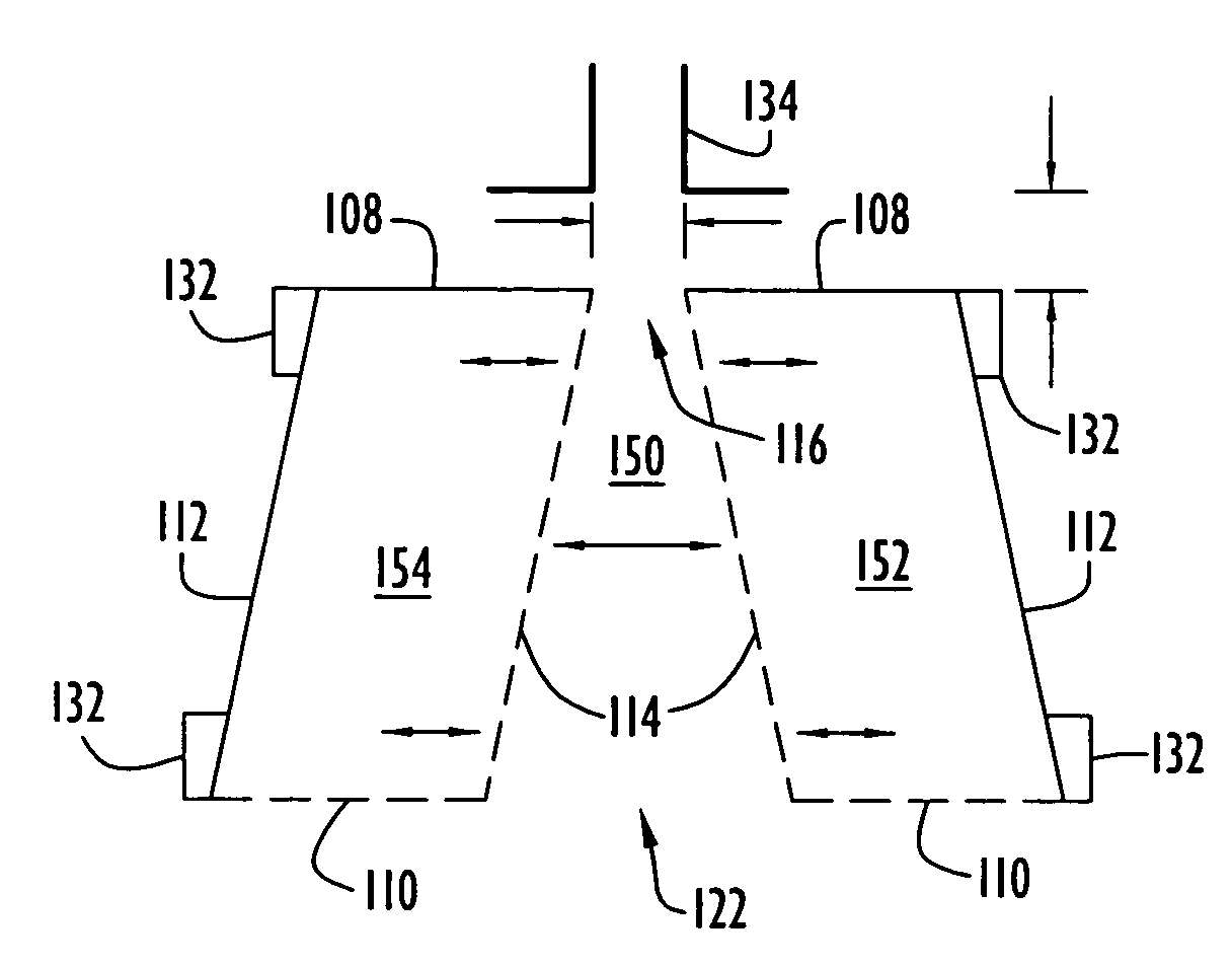
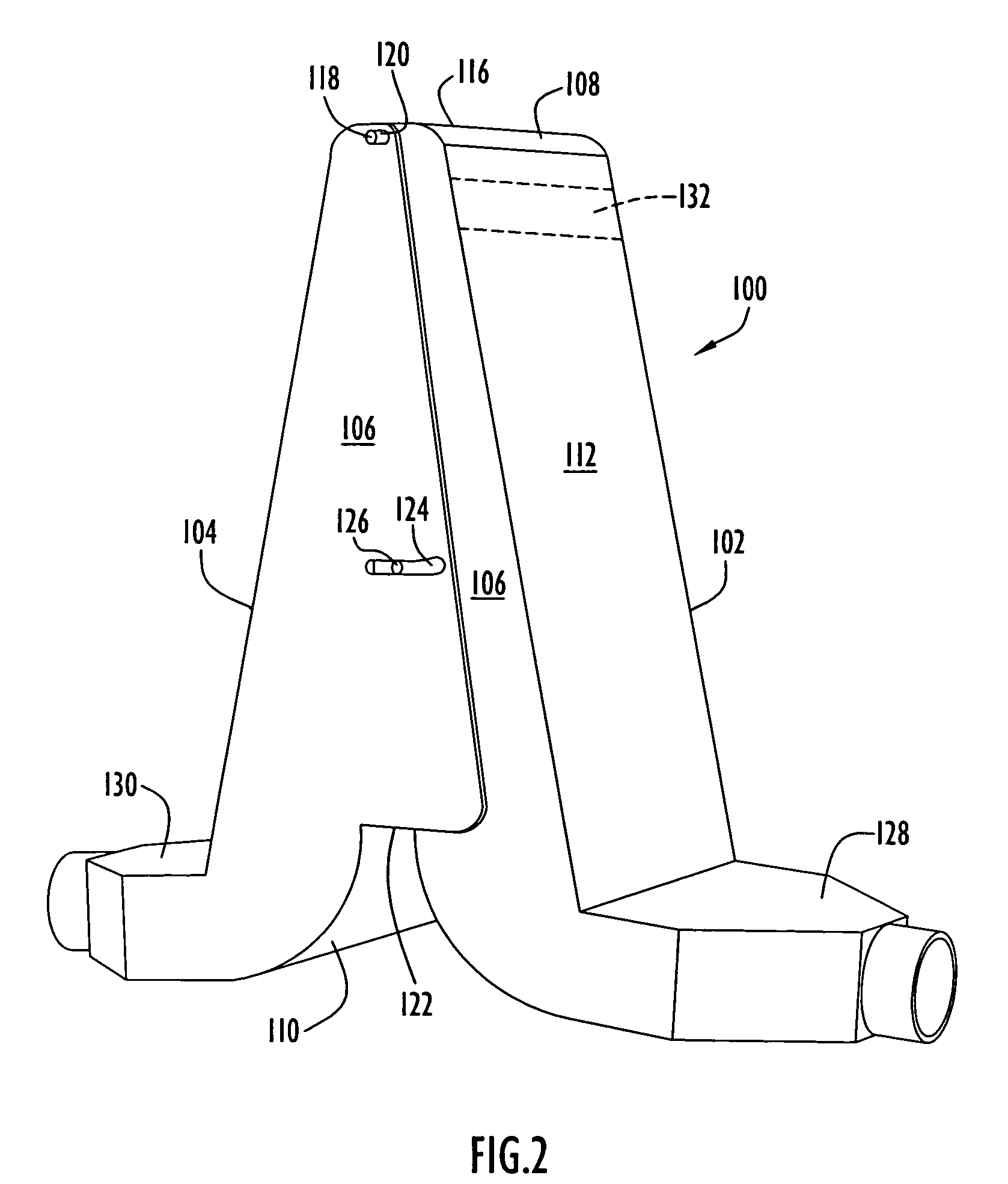
[0029]The following detailed explanations of FIGS. 2–10B and of the preferred embodiments reveal the methods and apparatus of the present invention. The present invention overcomes the aforementioned problems associated with excess air in fiber extrusion systems in an innovative and relatively low cost manner by introducing a device and methods for controlling airflow either by separating at least a portion of entrained air from extruded fibers or directing the airflow in a more controlled manner. The airflow control device controls the amount and velocity of air that is allowed to exit with the spun filaments into the fabric formation zone. This process allows for controlled recycling or other controlled handling of the bulk of the air. The device can also be adjusted to cause the high speed yarn filaments to decelerate to a substantially lower velocity before exiting into the fabric formation zone, and minimizing or even eliminating entrained air that is generated below the aspira...


PUM

PropertyMeasurementUnit
heightaaaaaaaaaa
heightaaaaaaaaaa
widthaaaaaaaaaa

Abstract

An apparatus for controlling airflow in a fiber extrusion process includes a fiber flow region between an inlet through which extruded fibers are received and an outlet through which the extruded fibers are discharged and at least one surface providing a boundary between the fiber flow region and another region, wherein the surface includes apertures permitting air to flow between the fiber flow region and the other region to control airflow at the outlet of the fiber flow region. The apparatus can include a housing which contains at least one chamber, with the surface forming a boundary between the fiber flow region and the chamber, such that the apertures permit air to flow between the fiber flow region and at the chamber. In a spunbond process, the airflow control device receives drawn filaments exiting an aspirator and deposits the filaments onto a web-forming surface with reduced air disturbance.

Description

CROSS REFERENCE TO RELATED APPLICATION[0001]This application claims priority from U.S. Provisional Patent Application Ser. No. 60 / 471,710 entitled “A Modified Spun Bond Process Having Improved Fiber and Web Laydown, Greater Versatility and Improved Economics,” filed May 20, 2003. The disclosure of this provisional patent application is incorporated herein by reference in its entirety.BACKGROUND OF THE INVENTION[0002]1. Field of the Invention[0003]The present invention relates to methods and apparatus for controlling airflow in a fiber extrusion system and, more particularly, to an airflow control device capable of selectively separating, removing, or re-directing air present in the system to control the flow of the air and fibers in a desired manner.[0004]2. Description of the Related Art[0005]A great deal of development work has ensued since the initial development of the spunbond process in 1959 by DuPont. Much of that work has centered around uniform laydown of the melt spun fibe...

Claims


Application Information

Patent Timeline
Patent Type & Authority Patents(United States)
IPC IPC(8): D01D5/092F24F
CPCD01D13/02D01D5/092D04H3/02
Inventor WILKIE, ARNOLD E.BRANG, JAMESDE LA HOZ, ANGEL ANTONIO
Owner HILLS CO
Why Eureka
Try Eureka