Beamforming using a backplane and passive antenna element

a backplane and antenna element technology, applied in the direction of antennas, antenna details, electrical equipment, etc., can solve the problems of poor antenna gain of corresponding cell phone antennas, inability to mitigate interference or reduce fading, and general inability of antennas used in these phones so as to reduce interference and fading, reduce the cost of manufacture, and facilitate assembly

Inactive Publication Date: 2006-05-02
IPR LICENSING INC
View PDF16 Cites 23 Cited by
  • Summary
  • Abstract
  • Description
  • Claims
  • Application Information

AI Technical Summary

Benefits of technology

[0019]The techniques of the present invention offer advantages over the prior art. For example, a combination of active antenna element and at least one passive antenna element can be employed to adjust directionality, gain and angular beamwidth of an input / output beam pattern. These few components can be easily assembled into a compact cellular device such as a portable telephone. Consequently, a compact cellular device including such a transceiver assembly can cost less to manufacture than alternative antenna devices, yet provide the benefits of reduced interference and fading not otherwise achieved using only a standard active element for transmitting and receiving RF signals. Use of a backplane in relation to the active antenna element can also enhance directionality.
[0020]Another benefit of supporting beamforming according to the principles of the present invention is the ability to more optimally communicate with a target such as a base station. Since directionality and gain control of an input / output pattern of a portable device supports reduced power output, a user positioned behind the backplane can be exposed to less radiation than if higher power output levels were used to transmit the same information to a target base station. Overall power consumption is also reduced since a lower power beam is necessary to transmit to a target receiver.
[0021]Use of a movable backplane with respect to active and passive antenna elements enables manufacturers to reduce the size of antenna devices for transmitting and receiving RF signals. For example, a form factor associated with an antenna assembly of a mobile phone device or handheld wireless device can be reduced even though the transceiver assembly provides enhanced transmission and reception capabilities.

Problems solved by technology

So much emphasis has been placed on reducing cell phone size that antenna gains of corresponding cell phone antennas are surprisingly poor.
Antennas used in these phones, therefore, generally do not have the ability to mitigate the effects of interference or reduce fading.
Consequently, the quality of communication can suffer as a result of reduced cell phone size.

Method used


Image

  • Beamforming using a backplane and passive antenna element
  • Beamforming using a backplane and passive antenna element
  • Beamforming using a backplane and passive antenna element

Examples


Embodiment Construction

[0033]A description of preferred embodiments of the invention follows.

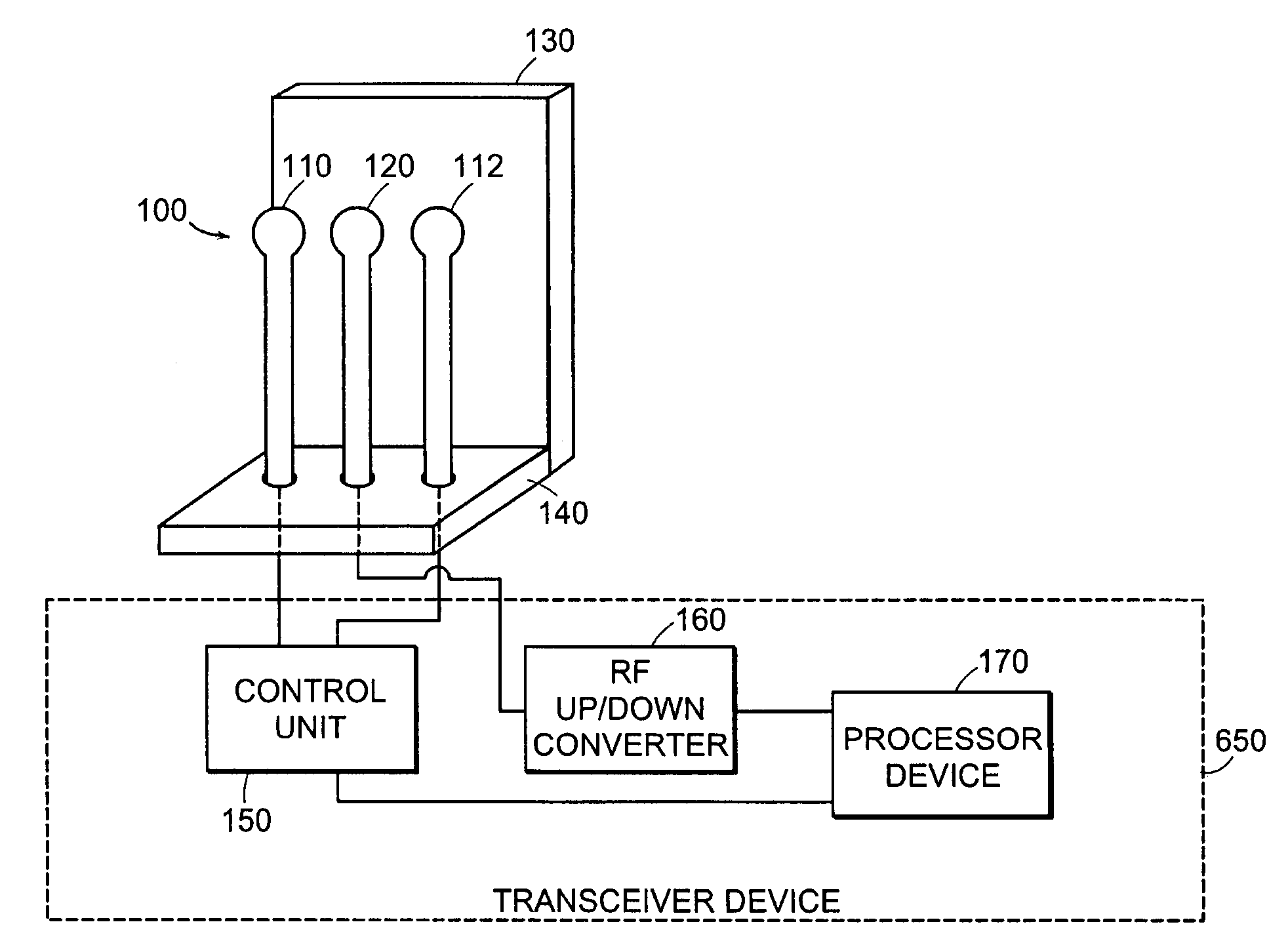
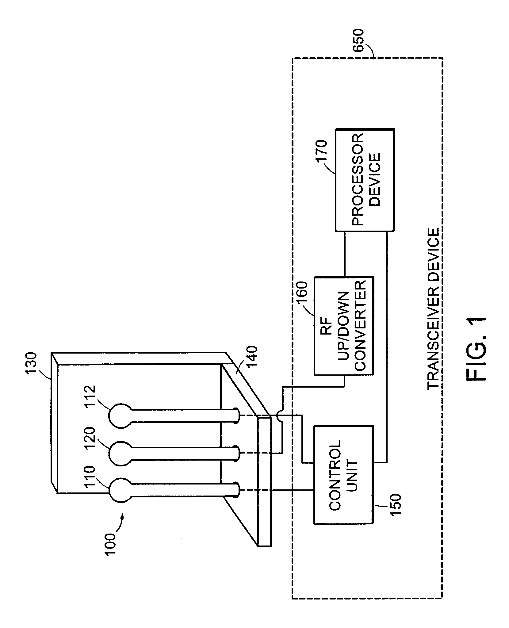
[0034]FIG. 1 is a block diagram and partial perspective view of antenna device 100 according to certain principles of a preferred embodiment. As shown, active antenna element 120 is disposed between passive antenna element 110 and passive antenna element 112. Both active antenna element 120 and passive antenna elements 110 and 112 are disposed on a similar side of backplane 130. In this embodiment, both active antenna element 120 and passive antenna elements 110 and 112 are fixed to base plane 140.

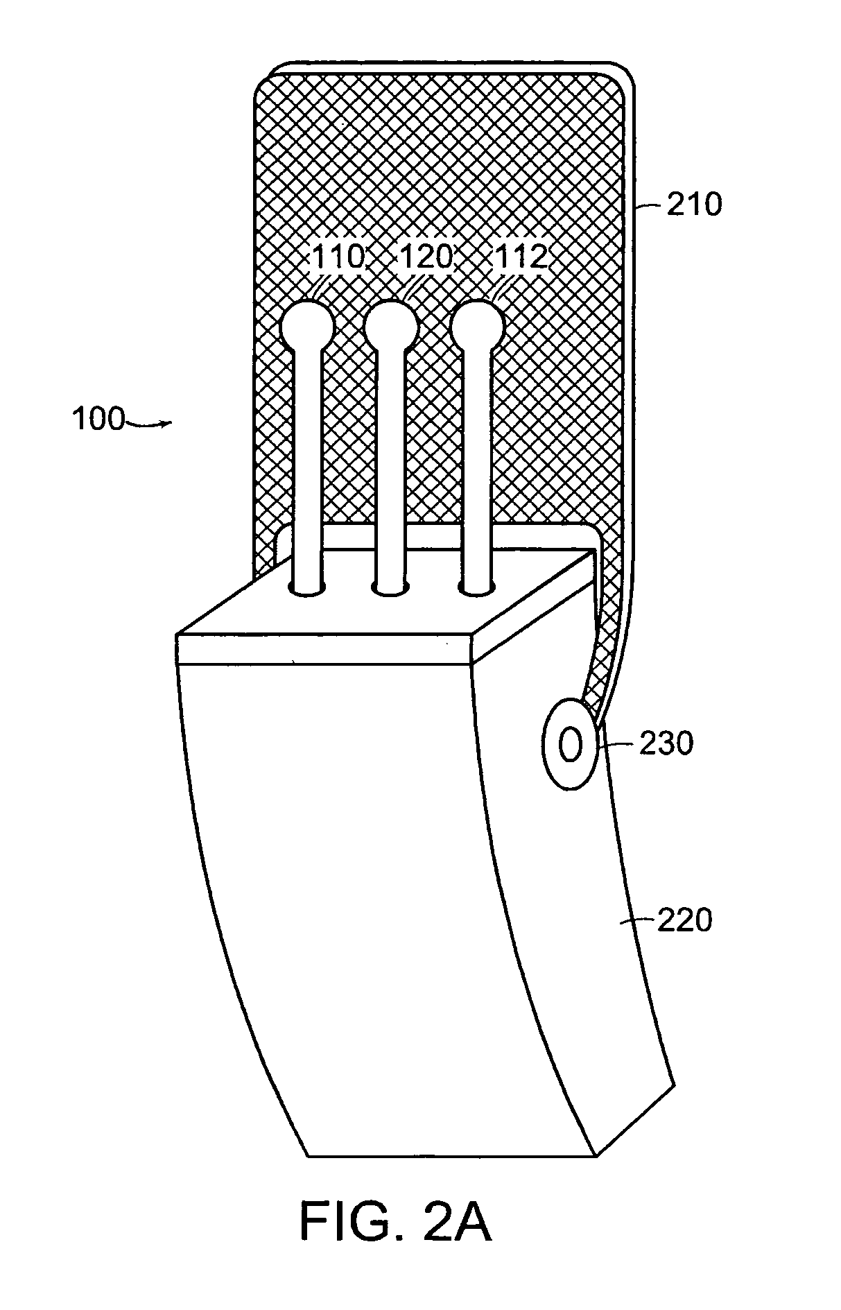
[0035]However, antenna device 100 can be fabricated so that some or all of the antenna elements are retractable or foldable for easy stowing. For example, some or all of the antenna elements can be automatically, manually, electronically or mechanically adjusted so that a corresponding device including antenna device 100 is compact when not in use, yet still functional when open and in use. Consequently, antenna elements...


PUM


Abstract

An active antenna element to transmit and/or receive RF (Radio Frequency) signals is positioned in relation to a backplane that reflects RF signals. One or more passive antenna elements can be disposed on a similar side of the backplane as the active antenna element. Settings of the one or more passive antenna elements are adjusted to produce an input/output beam pattern that varies depending on whether the at least one passive antenna element is reflective or transmissive. Based on this technique, an RF input output beam pattern of an antenna assembly including the backplane, active antenna element and passive antenna elements can be controlled for better reception and transmission of RF signals.

Description

RELATED APPLICATIONS[0001]This application claims the benefit of U.S. Provisional Application No. 60 / 350,904 filed on Jan. 23, 2002, entitled “Beamforming Using a Reflective Backplane and Passive Antenna Element”, the entire teachings of which are incorporated herein by reference.BACKGROUND OF THE INVENTION[0002]Cellular phones are continuously being reduced in size to enhance portability. For example, today's smallest available cellular phone device can conveniently fit in a person's pocket or clip easily onto a belt. The limit in size appears to be a cellular phone having dimensions similar or even smaller than those of a credit card so that it will fit in a wallet.[0003]So much emphasis has been placed on reducing cell phone size that antenna gains of corresponding cell phone antennas are surprisingly poor. Typically, antenna gains of smaller cellular phones are −3 dBi or even lower. Antennas used in these phones, therefore, generally do not have the ability to mitigate the effec...

Claims


Application Information

Patent Timeline
Patent Type & Authority Patents(United States)
IPC IPC(8): H01Q1/24H01Q3/44H01Q19/10H01Q19/28H01Q19/32
CPCH01Q3/446H01Q19/32H01Q19/10H01Q1/24H01Q3/26H01Q3/44
Inventor GOTHARD, GRIFFIN K.GAINEY, KENNETH M.CHIANG, BING
Owner IPR LICENSING INC
Why Eureka
Try Eureka