[0011]According to this method, in the first mode, display is performed at each of the pixels in accordance with the area gradation method according to the on-states or off-states of the sub-pixels. At that time, it is sufficient that a binary
signal designating a bit, according to which the sub-pixel is turned on or off, is used as the signal supplied to the data line. Therefore, it is difficult for such a signal to undergo the influence of the unevenness of the device characteristics and the wiring resistance. Thus, when the first mode is selected in the case of displaying a motionless image or an image subject to nominal motion, and in the case of displaying pixels having an equal gradation level in a
wide area, high-quality display thereof is realized without display unevenness.
[0014]According to the first aspect of the invention, preferably, the electro-optical apparatus has holding devices, which are provided correspondingly to each of the sub-pixels, that hold a corresponding bit of the gradation data. In this apparatus, the sub-pixels turn off once in the first mode regardless of data represented by the corresponding bit held in the holding devices. Thereafter, the sub-pixels turn on or off according to the bits of the gradation data, which are preliminarily held in the holding devices. According to this method, the sub-pixel is turned on or off according to the bit held by the holding device after the data to be displayed corresponding to the sub-pixel is reset to that corresponding to the off-state. Thus, it is unnecessary to rewrite the data that corresponds to the sub-pixel, whose on or off state is not changed, and that is held in the holding device. Therefore, there is no need to supply a bit to the first data line in a predetermined cycle. This enables high-quality display with low
power consumption.
[0015]Further, according to the method of the invention, preferably, the second
data lines are selected in a predetermined order in the second mode correspondingly to the sub-pixel corresponding to a selected row. Moreover, a voltage signal is applied to the selected second data line. According to this method, a circuit that supplies the voltage signal to the second data line can be simplified.
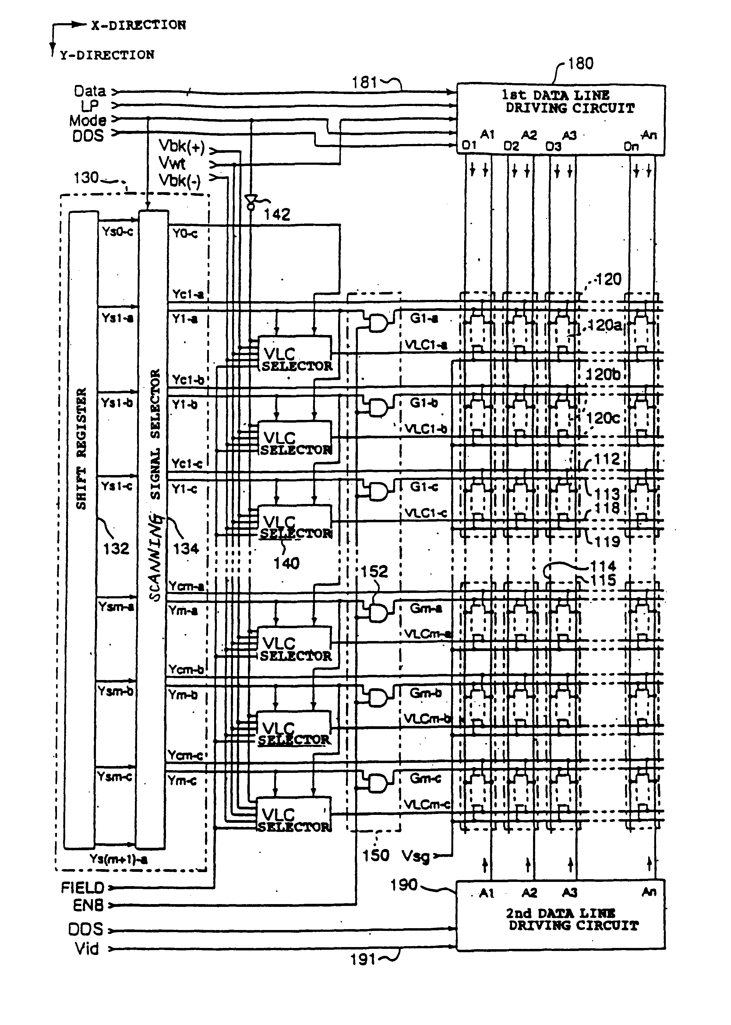
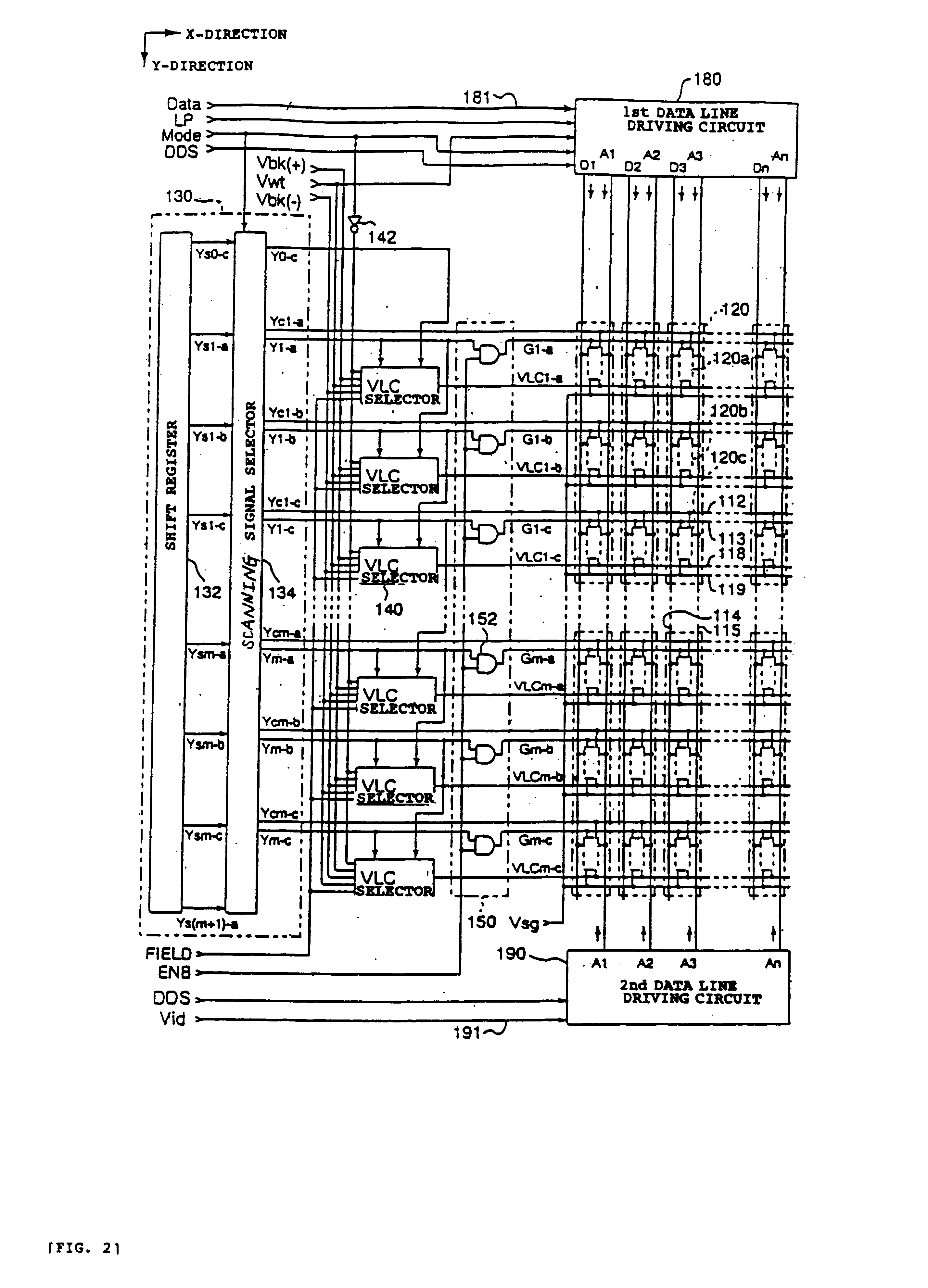
[0019]a data line driving circuit that outputs, in the first predetermined mode, a corresponding bit of gradation data representing a gradation level of a pixel including the sub-pixel, which corresponds to the intersection corresponding to the scanning line selected by the scanning line driving circuit, to a corresponding first data line and outputs, in the second mode, a voltage signal corresponding to a gradation level of the pixel to corresponding second
data lines that corresponds to the intersection corresponding to the sub-pixels grouped as one pixel. According to the second aspect of the invention, high-quality display with no display unevenness is enabled, similarly as in the case of the method of the first aspect of the invention. Moreover, enriched gradation display is realized.
[0024]According to the third aspect of the invention, preferably, the sub-pixel includes a first switch, adapted to turn on or off in the first mode according to a signal supplied to a write
control line provided correspondingly to each of the scanning lines, a holding device that holds, when the first switch turns on in the first mode, data according to a bit supplied to a corresponding one of the first
data lines, a second switch that selects, after a signal, which turning off the sub-pixel, is selected in the first mode regardless of data held in the holding device, a signal causing the sub-pixel to turn on or off according to the data held in the holding device, a third switch, which is adapted to turn on or off according to a scanning signal supplied to a corresponding one of the scanning lines in the second mode, that samples voltage signals supplied to the corresponding second data line, and a sub-pixel
electrode to which a signal selected by the second or third switch is applied. With this configuration, in the first mode, the sub-pixel is turned on or off according to the bit held by the holding device after the data to be displayed at the sub-pixel is once reset to the off-state thereof. Thus, it is unnecessary to rewrite the data that corresponds to the sub-pixel, whose on or off state is not changed, and that is held in the holding device. Therefore, there is no necessity to supply a bit to the first data line in a predetermined cycle. This enables high-quality display with low
power consumption. Incidentally, in the apparatus of this configuration, in the second mode, the third switch performs the sampling of the voltage signals supplied to the second data line.

