Supercharge Your Innovation With Domain-Expert AI Agents!

Label printer with label edge detector

a label printer and detector technology, applied in the direction of typewriters, instruments, power drive mechanisms, etc., can solve the problems of optical sensors having inherent limitations, causing net loss in web advance, and progressive misregistration of label image with respect to label edges

Inactive Publication Date: 2006-05-02
ZIH CORP
View PDF10 Cites 11 Cited by
  • Summary
  • Abstract
  • Description
  • Claims
  • Application Information

AI Technical Summary

Benefits of technology

"The present invention relates to thermal and thermal transfer label printers, and more specifically to improving the printing of labels on pressure-sensitive adhesive-backed labels. The invention addresses issues with current optical sensors and label edge sensors used in thermal printers, such as fluctuations in light intensity and errors caused by slack between the label and the platen roller. The invention provides a system and method that overcomes these deficiencies and improves the printing of labels on pressure-sensitive adhesive-backed labels."

Problems solved by technology

Slippage is a function of the web tension and produces a net loss in web advance, for example in an on-demand printer, when the printer advances a label against supply roll inertia to facilitate clearance from the printer for individual removal after printing and then backfeeds into a slack web before printing the next label.
Any error in web advance accumulates as successive labels are printed, resulting in progressive misregistration of the label image with respect to the label edges.
However, optical sensors have inherent limitations.
Even though the intensity of the light source is constant, the paper fibers in the label and in the backing produce fluctuations in the light intensity that may introduce errors into the edge determination.
Because the light source and or optical sensors are proximate the media path, they may be fouled over time by fibers or other detritus continuously introduced into the media path by the media.
Also, a transverse movement of the slack web perpendicular to its plane between the light source and the photocell may occur during backfeed, introducing an additional error.
If the web slips between the time the leading edge of a label passes the photocell and when it reaches the heater elements, or if slack develops between the photocell and the heater elements during backfeed, the printing will be misregistered on the label.
However, this configuration also has several limitations.
First, signals from the sensor may have a poor signal to noise ratio due to support structure flexure and or external vibrations transmitted to the print head by the printer frame, print head pivot connection and or the print head spring.
Further, use of different sized and or oriented labels, for example edge or center justified labels, may change the sensor response characteristics.

Method used


Image

  • Label printer with label edge detector
  • Label printer with label edge detector
  • Label printer with label edge detector

Examples


Embodiment Construction

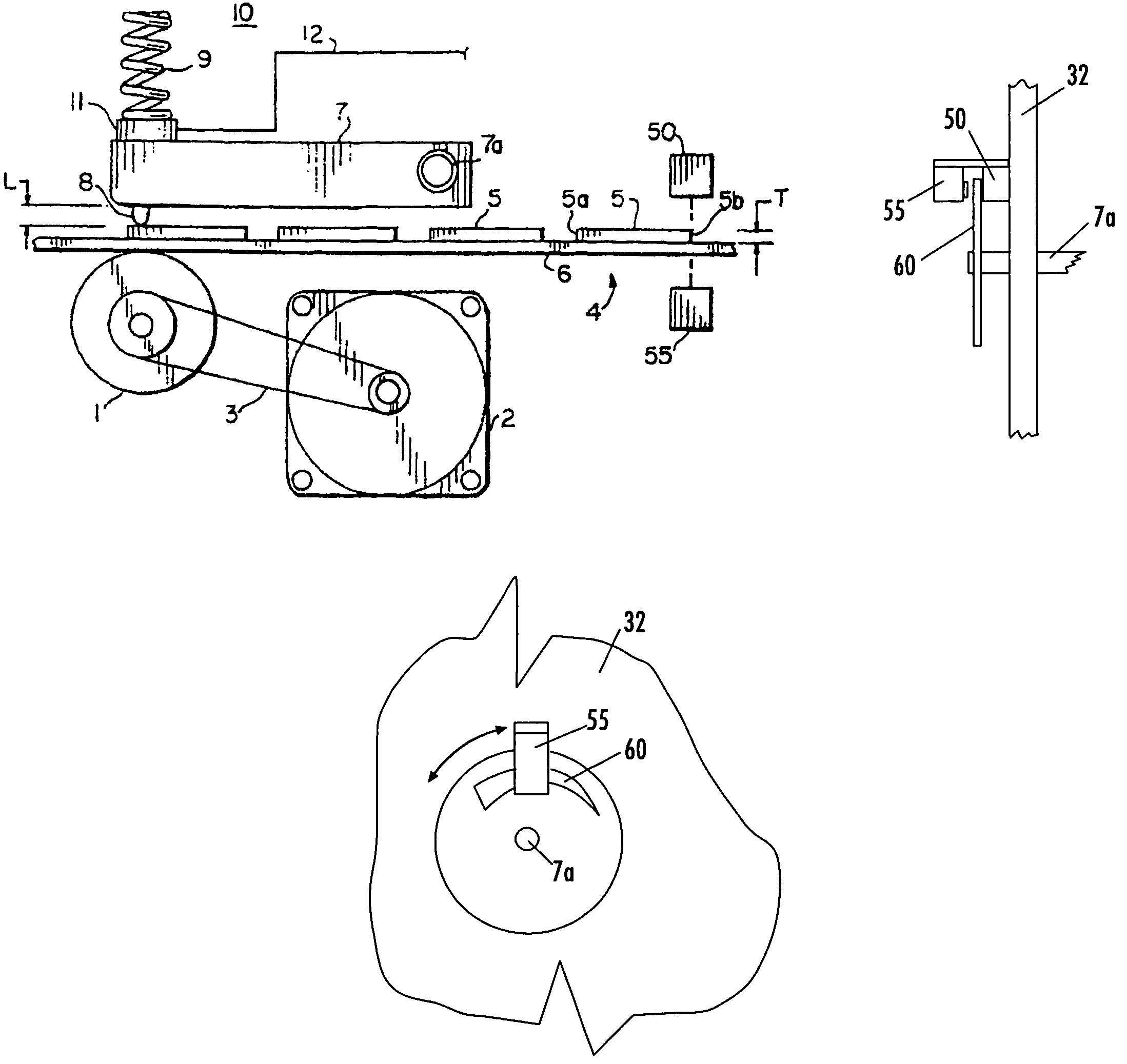
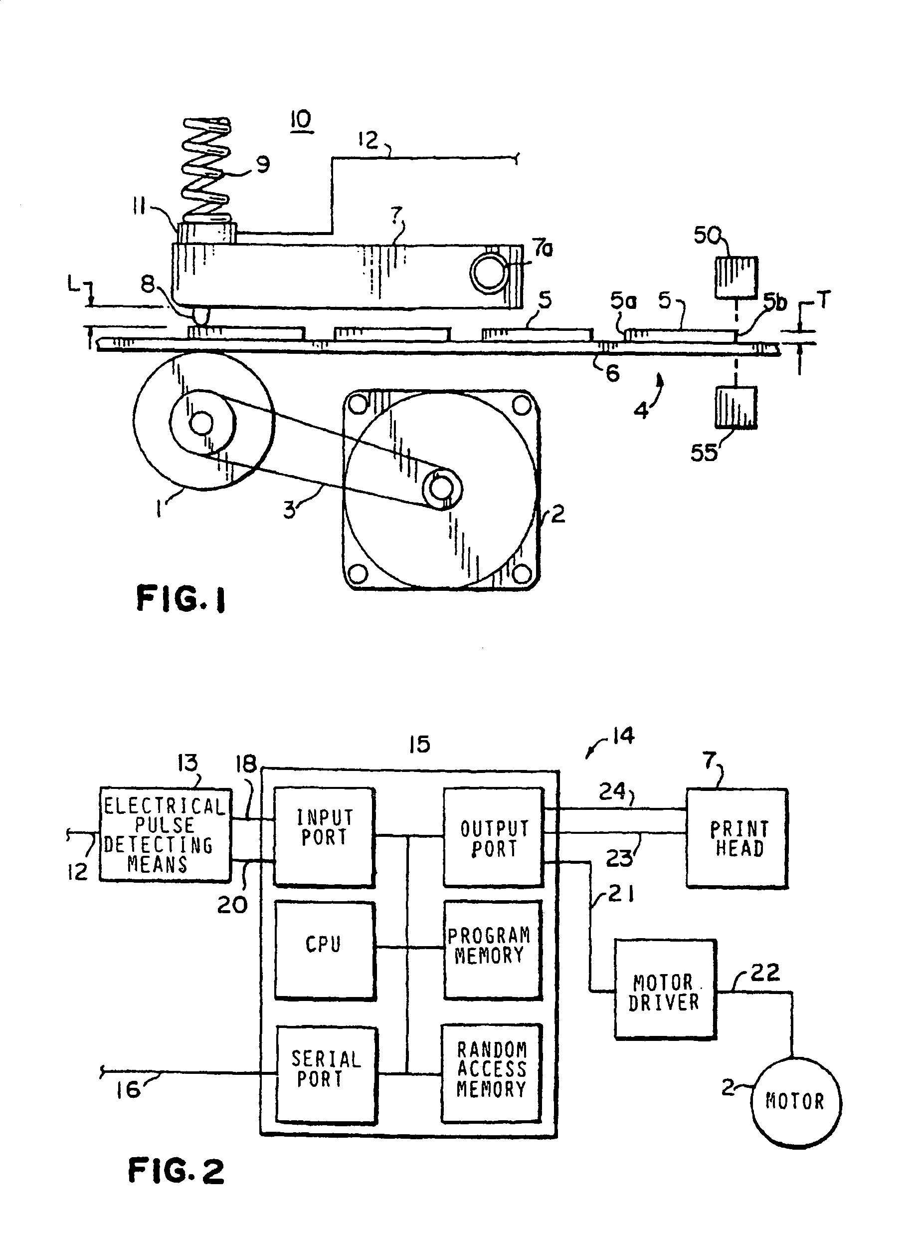
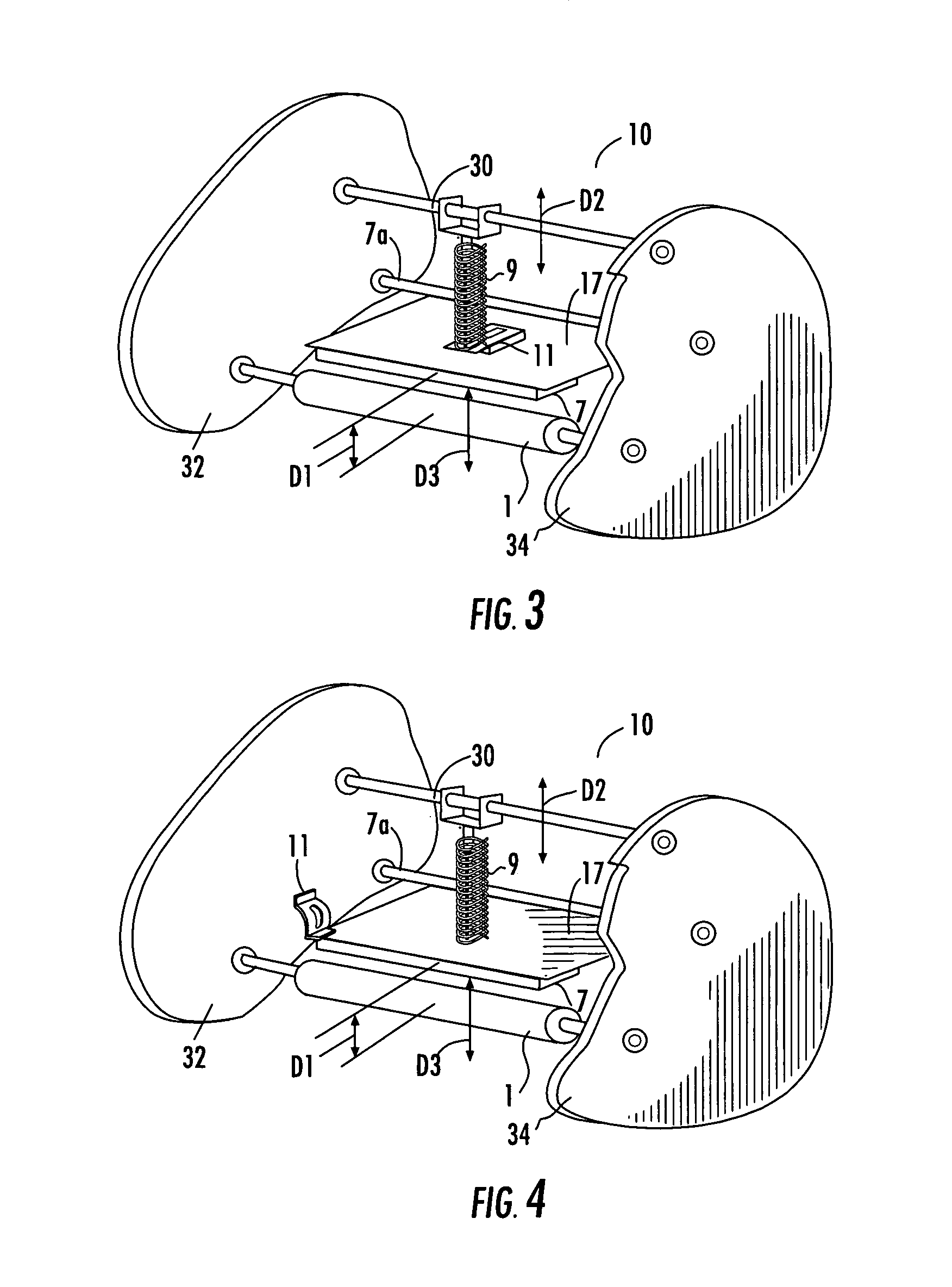
[0027]Applicant's prior U.S. Pat. No. 5,978,004, titled “Label Printer with Label Edge Sensor”, issued Nov. 2, 1999 and hereby incorporated by reference in the entirety, describes a label printer 10. As shown in FIG. 1, a driving mechanism for the label printer 10 includes a platen roller 1, driven by a stepper motor 2 through, for example, a belt and pulley drive 3 to advance a label web 4 having a plurality of label(s) 5 removably positioned on a backing 6. A print head assembly includes a thermal print head 7 of a prior art type having a line of heater elements 8. The print head assembly is pivotably supported by a pivot 7a such that the heater elements 8 are aligned transverse to the motion of the web 4. The heater elements 8 are pressed against web 4 and web 4 against platen 1 by the action of a bias mechanism, for example a spring 9, through a pressure transducer or sensor 11, having a sensor output lead 12. While the print head 7 is shown as directly connected to the pivot 7a...


PUM


Abstract

A label printer with a label edge sensor having a shortened measurement path through the supporting frame of the label printer. Linear and or angular movement of the print head as it encounters label edges is detected by sensors coupled to the printer frame. The sensor may be, for example, an optical, piezoelectric or position detecting transducer. In embodiments where the print head is rigidly coupled to a pivot that extends through the printer frame, the movement of the print head may be detected by a sensor located on the far side of the printer frame.

Description

BACKGROUND OF INVENTION[0001]1. Field of the Invention[0002]The present invention relates to thermal and thermal transfer label printers and, more specifically, to such printers adapted to printing on pressure sensitive adhesive-backed labels.[0003]2. Description of the Prior Art[0004]Thermal and thermal transfer printers are well known in the art. In thermal label printers, a web of pressure sensitive adhesive-backed labels, each having a thermally sensitized surface, is fed between a platen roller and a thermal print head. In a thermal transfer label printer, a transfer ribbon having a heat transferrable ink layer is additionally interposed between the print head and the label so that non-sensitized labels may be printed. The transfer ribbon is flexible and typically no thicker than ten microns Thus, the principles of the present invention are equally applicable to thermal and thermal transfer printers.[0005]Pressure sensitive adhesive-backed labels for automated printing are typi...

Claims


Application Information

Patent Timeline
Patent Type & Authority Patents(United States)
IPC IPC(8): B41J2/315B41J2/32B41J3/407B41J11/00B41J25/304
CPCB41J3/4075B41J25/304B41J11/0095
Inventor EHRHARDT, ROBERT
Owner ZIH CORP
Features
  • R&D
  • Intellectual Property
  • Life Sciences
  • Materials
  • Tech Scout
  • Unparalleled Data Quality
  • Higher Quality Content
  • 60% Fewer Hallucinations
Learn More