
Memory interface control circuit and memory interface control method

a control circuit and memory technology, applied in the field of memory interface control circuit and memory interface control method for reading data from a memory, can solve the problems of difficult to determine the timing at which the receiver accepts data, and the placement of a plurality of rams is still restricted, and achieves high glitch noise resistance

Active Publication Date: 2006-05-02
NEC CORP
View PDF10 Cites 45 Cited by
  • Summary
  • Abstract
  • Description
  • Claims
  • Application Information

AI Technical Summary

Benefits of technology

The present invention provides a memory interface control circuit and method that can relax a RAM placement restriction and ensure high glitch noise resistance. The circuit includes a secondary data strobe signal generating circuit that generates a secondary data strobe signal that is stable when the data in each time slot is stable. The circuit also includes an auxiliary signal generating circuit that causes the mask signal to change from a disable level to an enable level for a short period of time. The buffer circuit stores data of all time slots using the secondary data strobe signal. The technical effect of this invention is to improve the performance and reliability of memory interface control.

Problems solved by technology

If the wiring lengths from the memory (DDR SDRM) to a controller are different, time required until data reaches to a receiver (flight time) is also different, thereby, it is difficult to determine a timing at which the receiver accepts data.
Even if the mask is set at a specific timing to prevent the glitch noise from being superimposed on the DQS, the placement of a plurality of RAMs are still restricted.

Method used


Image

  • Memory interface control circuit and memory interface control method
  • Memory interface control circuit and memory interface control method
  • Memory interface control circuit and memory interface control method

Examples


Embodiment Construction

[0046]A preferred embodiment of the present invention will be described hereinafter in detail with reference to the accompanying drawings.

[0047]The present invention is characterized in that a glitch noise resistance of a data strobe signal (DQS) can be improved in data transfer between a memory (particularly a DDR2-SDRAM) and a LSI, and in that a physical placement restriction relative to the LSI with which the memory performs the data transfer.

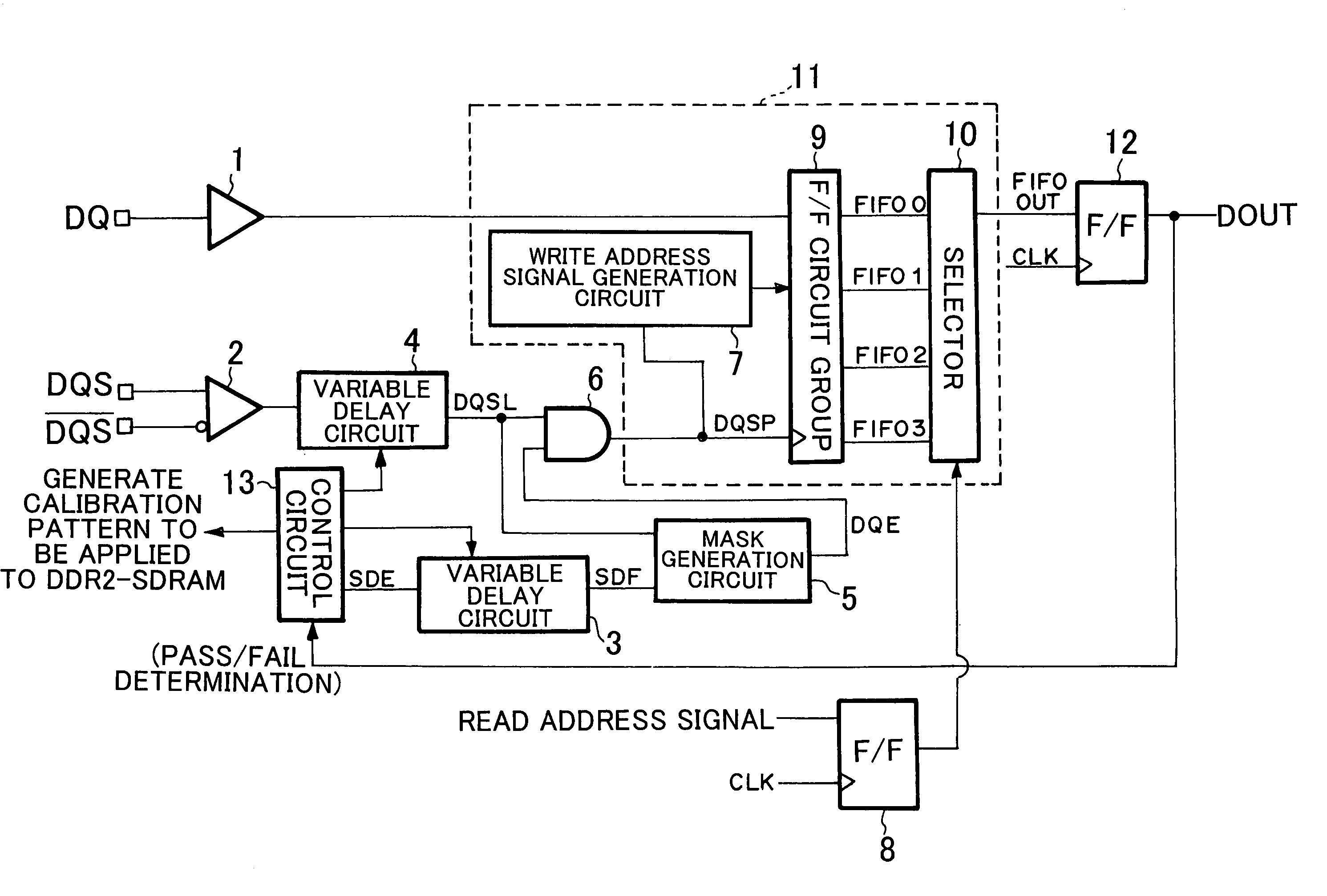
[0048]FIG. 6 is a block diagram that depicts a configuration of a memory interface control circuit according to the embodiment of the present invention. In FIG. 6, an I / O buffer 1 is an input buffer that receives data read from the DDR2-SDRAM. An I / O buffer 2 is an input buffer that receives a data strobe signal DQS read from the SDR2-SDRAM. The data strobe signal DQS is a balance input / output in the SDR2-SDRAM. Although the I / O buffers 1 and 2 are originally bidirectional buffers, they are illustrates as input buffers since this embodiment ...


PUM


Abstract

According to one embodiment, one variable delay circuit adjusts a data strobe signal to be delayed, a control circuit generates an auxiliary signal, another variable delay circuit adjusts the auxiliary signal to be delayed, a mask generation circuit generates a mask signal based on the delayed data strobe signal and the delayed auxiliary signal, and an AND circuit applies the mask signal to the delayed data strobe signal, thereby generating a data strobe signal without a glitch. A write address signal generation circuit generates a control signal for controlling a flip-flop group based on the data strobe signal without the glitch, and the flip-flop group stores read data according to the control signal. A selector selects data from among pieces of data stored in the flip-flop group according to the read address signal.

Description

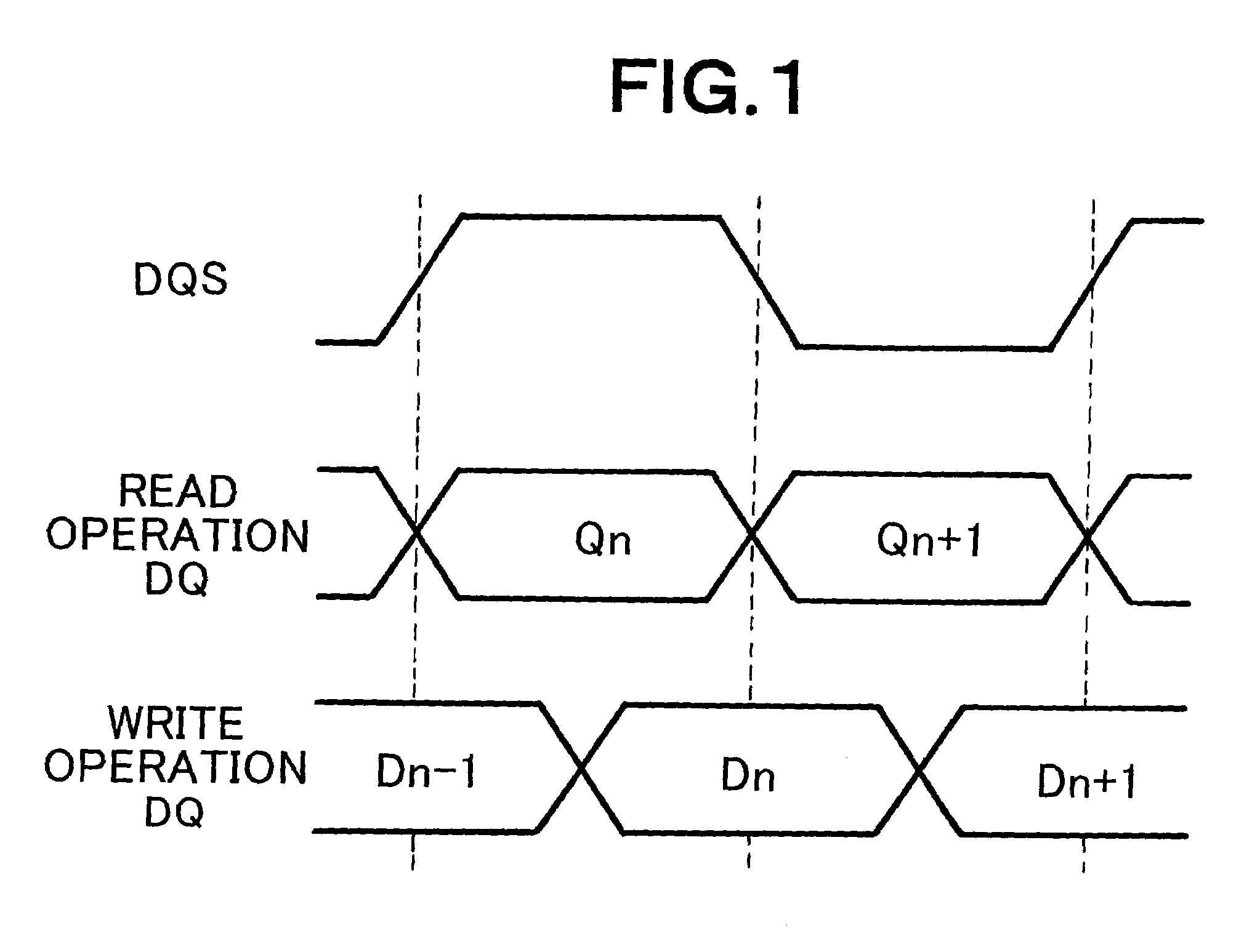
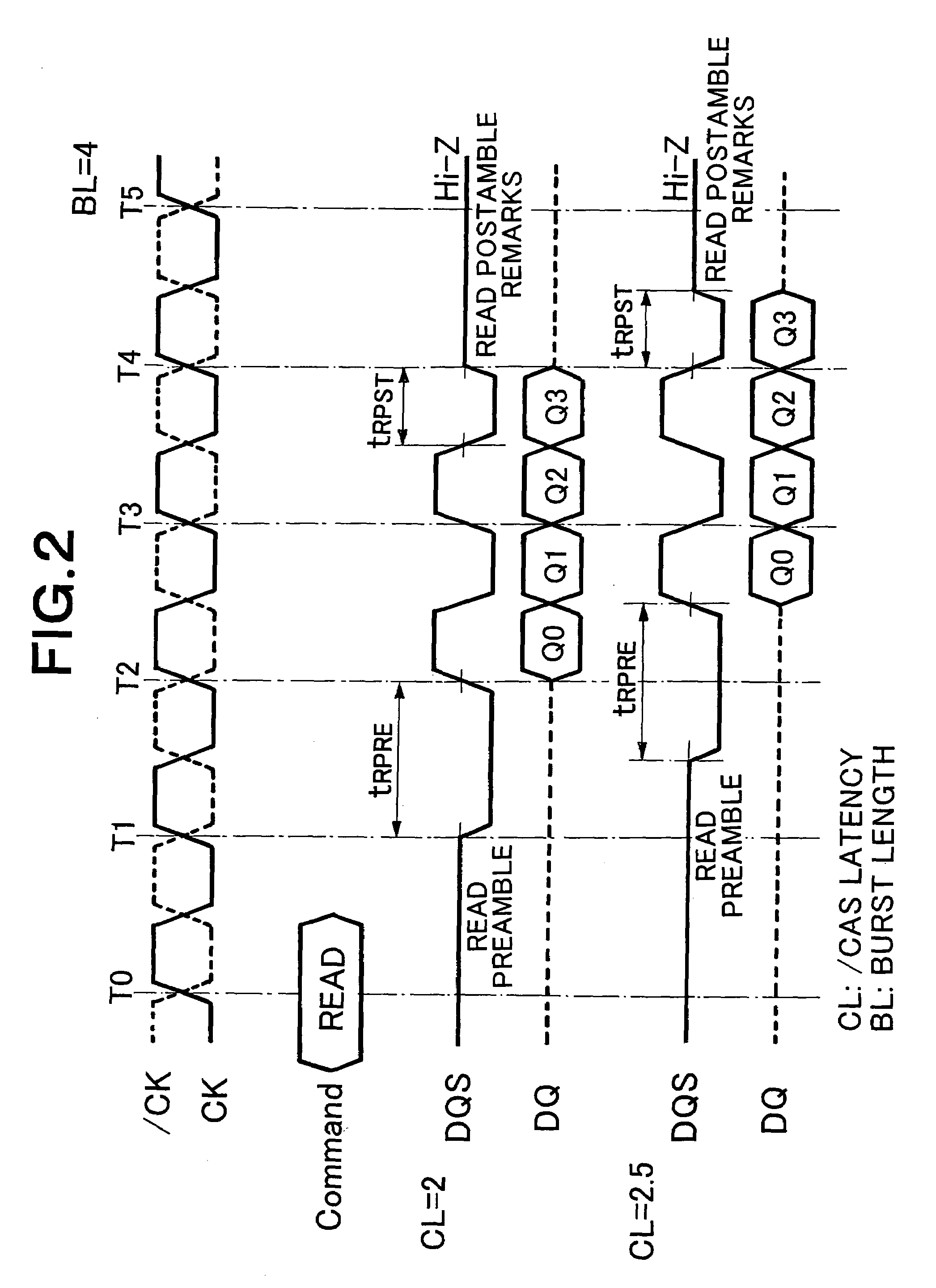
BACKGROUND OF THE INVENTION[0001]1. Field of the Invention[0002]The present invention relates to a memory interface control circuit and memory interface control method for reading data from a memory. More specifically, the present invention relates to a memory interface control circuit and memory interface control method for reading data from a double data rate 2-synchronous random access memory (hereinafter, “DDR2-SDRAM”).[0003]2. Description of the Related Art[0004]DDR-SDRAM has experienced substantial growth over the past several years. The DDR-SDRAM is a synchronous dynamic random access memory (“synchronous DRAM” or “SDRAM”) having a high-rate data transfer function called “double data rate (“DDR”) mode”. In the DDR mode, data can be read and written at both rising and falling of a clock signal which is provided for synchronizing respective circuits in a computer.[0005]The DDR-SDRM inputs and outputs data at a frequency twice as high as that of an external clock, so that a widt...

Claims


Application Information

Patent Timeline
Patent Type & Authority Patents(United States)
IPC IPC(8): G11C7/00G11C7/10G11C7/22G11C11/407
CPCG11C7/1051G11C7/1066G11C7/106G11C2207/2254A47G19/2227A47G19/2272A47G2200/106A47G2019/2294
Inventor AOKI, MUTSUMI
Owner NEC CORP
Learn More