Receiving apparatus and gain control method

a technology of receiving apparatus and gain control, which is applied in the direction of power management, transmission monitoring, multiplex communication, etc., can solve the problems of deterioration in the above interference suppression effect, and deterioration in the interference suppression effect, so as to prevent deterioration in the received quality and good accuracy

Inactive Publication Date: 2006-05-02
PANASONIC CORP
View PDF19 Cites 28 Cited by
  • Summary
  • Abstract
  • Description
  • Claims
  • Application Information

AI Technical Summary

Benefits of technology

[0019]The object of the present invention is to provide a receiving apparatus and a gain control method, which may perform

Problems solved by technology

And, the low bit-accuracy in the above desired signal S causes deterioration in the interference-suppression effect, and the above interference-suppression effect is also deteriorated in the case of reduction in the bit accuracy of the interference signal Iintra of the own cell, when a MUD (Multi User Detection) type interference canceller is used as an interference canceller.
Accordingly, when ratios of the desired signal S, and the interference signal Iintra of the own cell included in the received signal R are small, the bit accuracy of the above signals becomes insufficient to cause deterioration in the received quality.
On the other hand, when AGC is performed so that clipping receiving is performed with

Method used


Image

  • Receiving apparatus and gain control method
  • Receiving apparatus and gain control method
  • Receiving apparatus and gain control method

Examples


embodiment 1

[0040]FIG. 5 is a block diagram showing a configuration of a receiving apparatus according to an embodiment 1 of the present invention.

[0041]In the receiving apparatus of FIG. 5, a receiving RF section 102 amplifies a radio frequency signal received through an antenna 101, and performs frequency conversion of the above amplified signal into a baseband one. An AGC section 103 controls the gain of the above baseband signal output from the above receiving RF section 102 according to a gain coefficient input from a digital-to-analog conversion section 114 which will be described later. An analog-to-digital conversion section 104 converts the output signal of the above AGC section 103 into a digital signal.

[0042]A code storage section 105 stores primary codes allocated to the own cell. A code generation section 106 outputs the primary codes stored in the above code storage section 105 at a predetermined timing.

[0043]A despreading section 107 measures a delay profile by correlation betwee...

embodiment 2

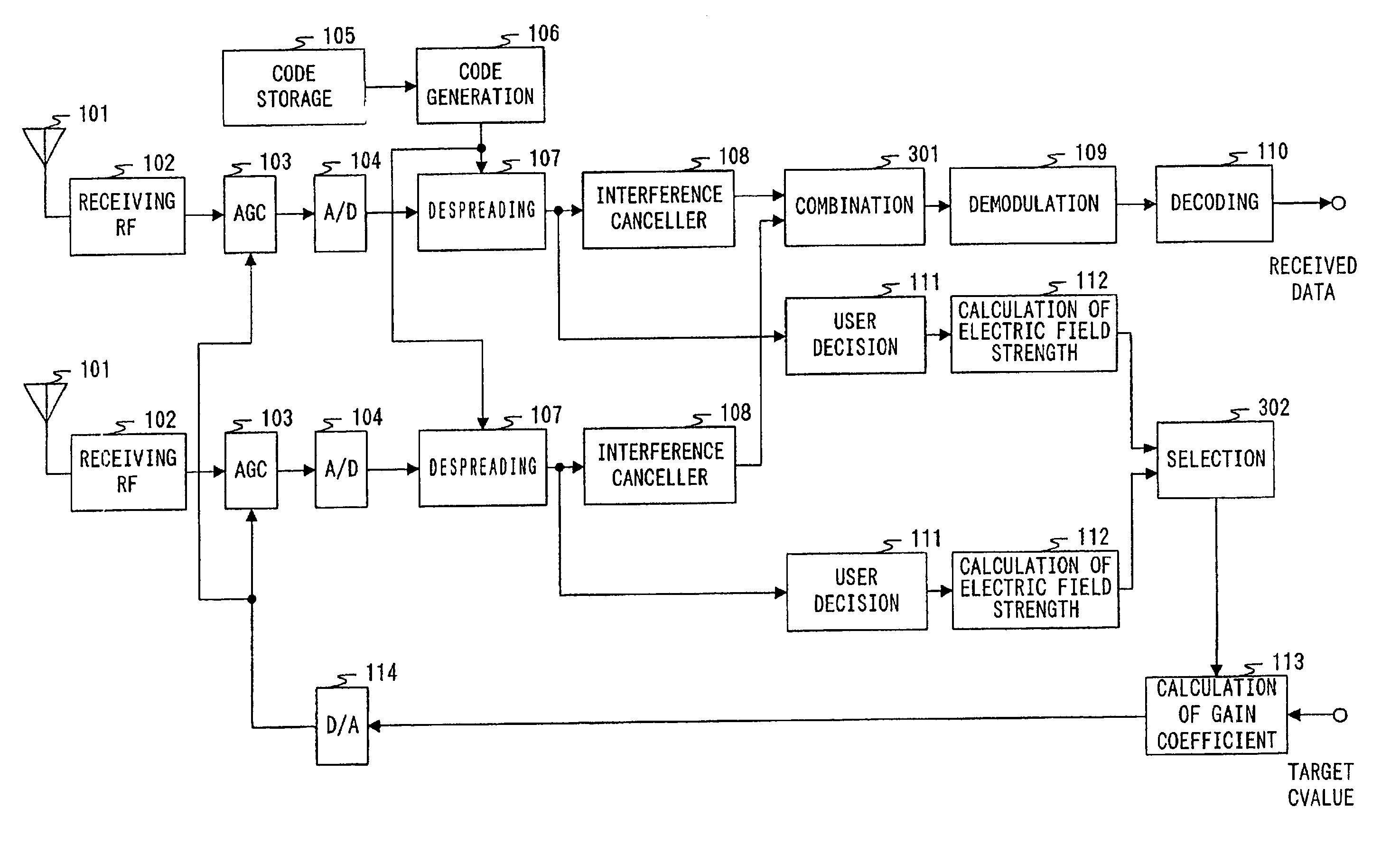
[0056]FIG. 8 is a block diagram showing a configuration of a receiving apparatus according to an embodiment 2 of the present invention. However, in the receiving apparatus shown in FIG. 8, components common to those of the receiving apparatus shown in FIG. 5 are denoted by the same reference numbers as those in FIG. 5, and detailed description will be eliminated.

[0057]Comparing with the receiving apparatus shown in FIG. 5, the receiving apparatus shown in FIG. 8 has a configuration comprising a pair of the following components: antennas 101; receiving RF sections 102; AGC sections 103; analog-to-digital conversion sections 104; code storage sections 105; code generation sections 106; despreading sections 107; interference cancellers 108; user judgment sections 111; and electric-field-strength calculation sections 112, and further including a combination section 301; and a selection section 302.

[0058]The above combination section 301 combines two outputs from the interference cancell...

embodiment 3

[0062]In a conventional receiving apparatus and gain control method, AGC with the same gain coefficient has been performed at handover from a base station under communication (hereinafter, called as “a first base station”) and to a base station newly to be communicated (hereinafter, called “a second base station”). In this case, there is caused insufficient bit-accuracy in the bit accuracy of the desired signal S and the interference signal Iintra of the own cell, when there is a difference in the number of users under communication between the first base station and the above second base station, and, conversely, the received quality is deteriorated, as the clipping is performed even for these signals. The present embodiment 3 will be described for a case where the above problems are solved, and deterioration in the received quality at handover is prevented.

[0063]FIG. 9 is a block diagram showing a configuration of a receiving apparatus according to the embodiment 3 of the present ...


PUM


Abstract

A code generation section 106 outputs a primary code stored in a code storage section 105 at a predetermined timing. A despreading section 107 measures a delay profile by correlation between the output signals of an analog-to-digital conversion section 104 and the primary codes of the above code generation section 106. A user judgment section 111 detects a maximum path for each user, based on the above delay profiles. An electric-field-strength calculation section 112 calculates the sum of amplitude values Rcell of the own cell from an electric power Pi of the maximum path PAi for each user i. A gain-coefficient calculation section 113 calculates a gain coefficient so that the above Rcell becomes equal to a target value. Thereby, AGC may be performed with good accuracy, and deterioration in the received quality may be prevented, when an MUD type interference canceller is used.

Description

[0001]This application is a 371 of PCT / JP01 / 02145 filed on Mar. 19, 2001.TECHNICAL FIELD[0002]The present invention relates to a receiving apparatus and a gain control method, which are used for a digital radio communication system such as a cellular telephone, and a car telephone.BACKGROUND ART[0003]In a digital radio communication system, such as a cellular telephone and a car telephone, which has drastically become very important in recent years, a base station set up in each cell allocates radio communication channels to a plurality of communication terminals existing in a cell and at the same time communicates by radio with the above terminals.[0004]FIG. 1 is a view showing a configuration of a digital radio communication system. It is supposed in FIG. 1 that base stations 11 through 13 are set up in cells 21 through 23, respectively. Mobile stations 31 through 33 are supposed to be located in the above cell 21 at present, and to be under radio communication with the above base...

Claims


Application Information

Patent Timeline
IPC IPC(8): H04B1/69H03G3/20H04B1/12H04B1/16H04B1/707H04B1/7103H04B7/005H04J13/00
CPCH04B1/707H04B1/7107H04W52/343H04B17/364H04W52/52H04B17/318H04W52/346
Inventor TAKAHASHI, HIDEYUKI
Owner PANASONIC CORP
Why Eureka
Try Eureka