Equalization for audio mixing

a technology of equalization and mixing, applied in the field of audio signal processing, can solve the problems of loss of spectral energy and/or loudness, inability to apply, and inability to provide satisfactory results

Active Publication Date: 2006-05-02
AVAGO TECH INT SALES PTE LTD
View PDF4 Cites 45 Cited by
  • Summary
  • Abstract
  • Description
  • Claims
  • Application Information

AI Technical Summary

Benefits of technology

[0014]According to yet another embodiment, the present invention is an apparatus for mixing an N-channel input audio signal to generate an M-channel output audio signal, where N and M are positive integers. The apparatus comprises a mixer, one or more loudness estimators, and an equalizer. The mixer is configured to mix N input channel signals corresponding to the N-channel input audio signal to generate M mixed channel signals. The one or more loudness estimators are configured to generate a first loudness measure for the N-channel input audio signal and a second loudness measure for the M mixed channel signals. The equalizer is configured to equalize the M mixed channel signals based on the first and second loudness measures to generate the M-channel output audio signal.

Problems solved by technology

A common problem in many areas of audio recording, audio production, and audio coding is the mixing of a number of input audio channels to generate a different number of output audio channels.
One drawback of such mixing techniques is a possible loss of spectral energy and / or loudness when some of the spectral components of the input audio channels are not aligned in phase.
Although these techniques tend to reduce the coloration effect for particular situations, there are many audio processing applications in which these techniques either cannot be applied and / or will not provide satisfactory results.

Method used


Image

  • Equalization for audio mixing
  • Equalization for audio mixing
  • Equalization for audio mixing

Examples


Embodiment Construction

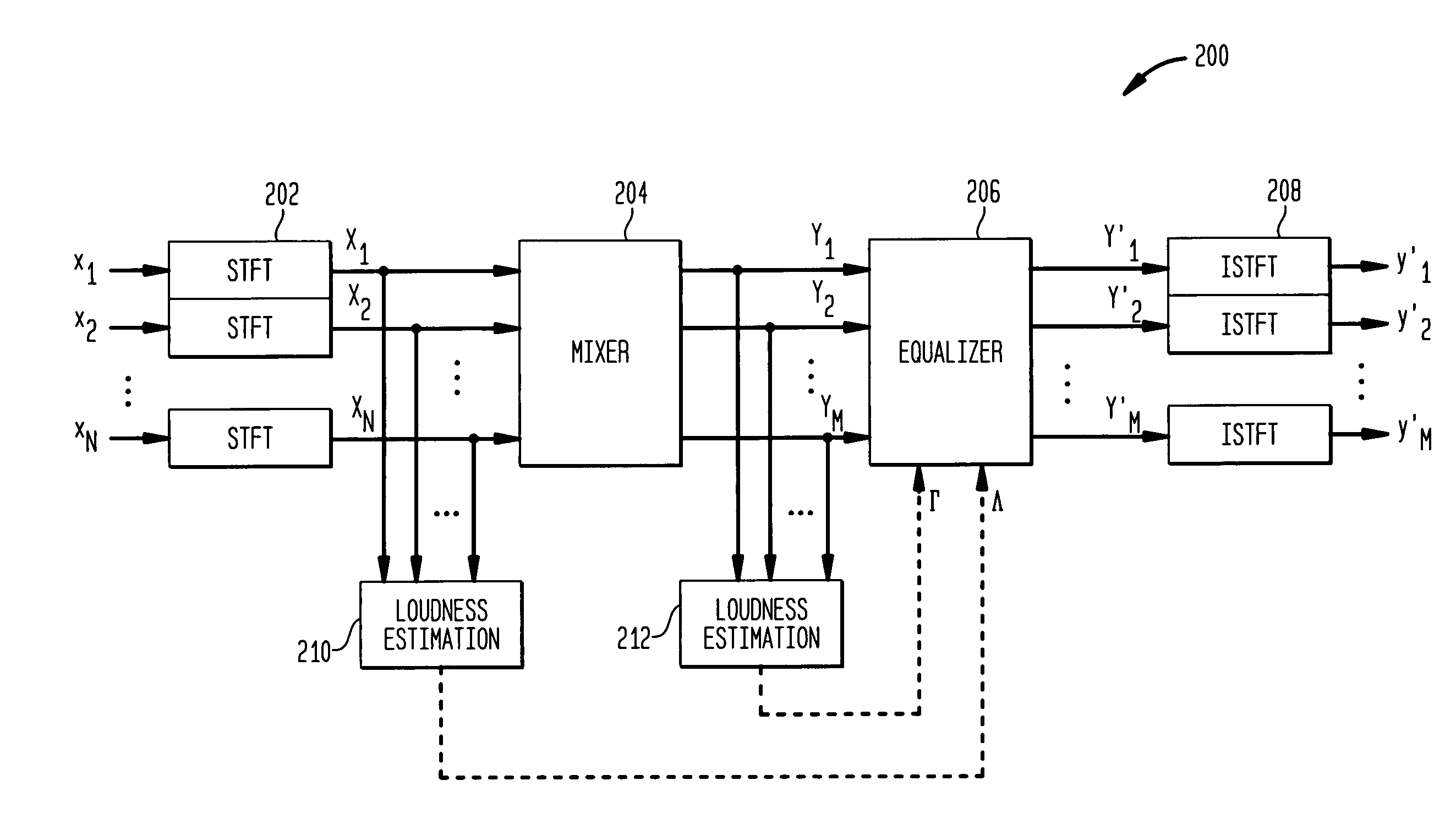
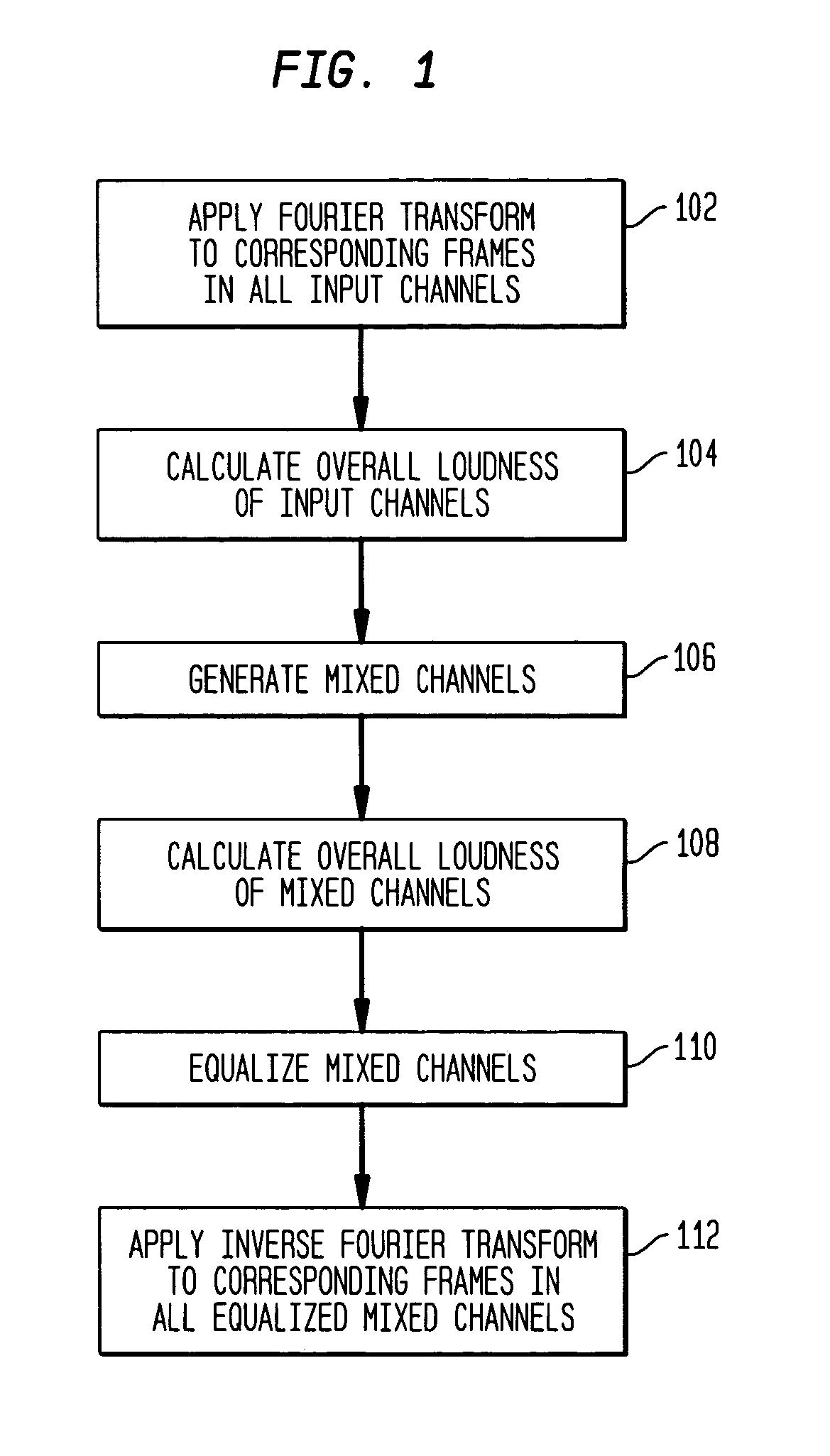
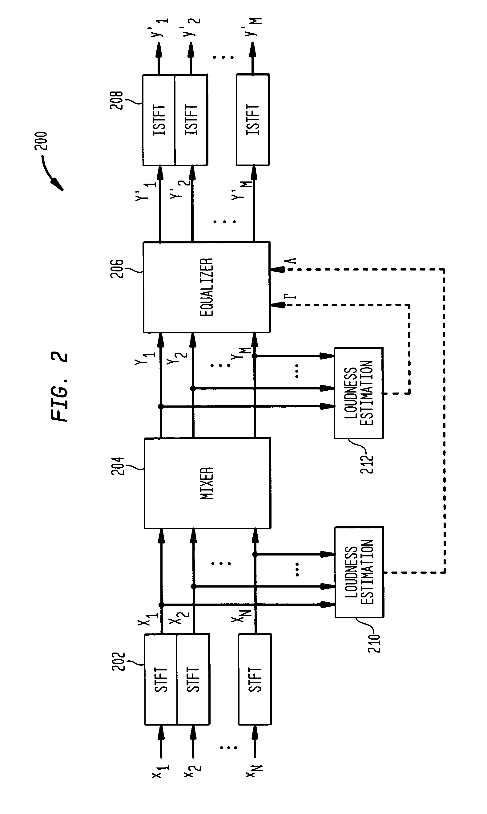
[0018]FIG. 1 shows a flow diagram of an equalized mixing procedure, according to one embodiment of the present invention. In particular, the processing of FIG. 1 corresponds to the mixing of an N-channel input signal to generate an M-channel output signal, where the input signal has N time-domain channel signals xn(t), n=1, . . . , N, and the output signal has M time-domain channel signals y′m(t), m=1, . . . , M. For down-mixing applications, N>M≧1. For example, when down-mixing a stereo input signal to a mono output signal, N=2 and M=1. For up-mixing applications, 1≦N2).

[0019]According to the processing of FIG. 1, a short-time Fourier transform (STFT) is applied to frames of each time-domain input channel signal (step 102), where the complex STFT transform of a short-time frame with index k of input channel signal xn,k(t) is denoted as Xn,k(ω). In order to improve the spectral resolution, the STFT transform preferably includes the application of a window function when generating ea...


PUM


Abstract

During mixing of an N-channel input signal to generate an M-channel output signal, the mixed channel signals are equalized (e.g., amplified) to maintain the overall energy/loudness level of the output signal substantially equal to the overall energy/loudness level of the input signal. In one embodiment, the N input channel signals are converted to the frequency domain on a frame-by-frame basis, and the overall spectral loudness of the N-channel input signal is estimated. After mixing the spectral components for the N input channel signals (e.g., using weighted summation), the overall spectral loudness of the resulting M mixed channel signals is also estimated. A frequency-dependent gain factor, which is based on the two loudness estimates, is applied to the spectral components of the M mixed channel signals to generate M equalized mixed channel signals. The M-channel output signal is generated by converting the M equalized mixed channel signals to the time domain.

Description

CROSS-REFERENCE TO RELATED APPLICATIONS[0001]This application claims the benefit of the filing date of U.S. provisional application No. 60 / 391,095, filed on Jun. 24, 2002.BACKGROUND OF THE INVENTION[0002]1. Field of the Invention[0003]The present invention relates to audio signal processing and, in particular, to mixing audio signals.[0004]2. Description of the Related Art[0005]A common problem in many areas of audio recording, audio production, and audio coding is the mixing of a number of input audio channels to generate a different number of output audio channels. The change in the number of channels can be motivated by, e.g., a difference between the number of audio tracks (channels) of the recording device and the number of channels supported by the playback system or a difference between the number of channels of the distribution medium (e.g., CD, DVD, radio) and the number of channels supported by the playback system.[0006]One example is FM radio where audio is usually delive...

Claims


Application Information

Patent Timeline
Patent Type & Authority Patents(United States)
IPC IPC(8): H04B1/00H04R3/00G10L15/22G10L19/00G10L19/02H03F3/181H03G5/16H04S1/00H04S3/00H04S5/00
CPCG10L15/22G10L19/008H04S3/00H04S5/005H04S1/007G10L19/0212H04S2420/03
Inventor BAUMGARTE, FRANK
Owner AVAGO TECH INT SALES PTE LTD
Why Eureka
Try Eureka