System and method for three-dimensional surface inspection

a three-dimensional surface and inspection system technology, applied in the field of three-dimensional surface inspection, can solve the problems of slow and inefficient process, computer detection of defective objects, and rapid and efficient obtaining detailed and accurate information about the height of structures

Inactive Publication Date: 2006-05-02
RUDOLPH TECHNOLOGIES INC
View PDF10 Cites 27 Cited by
  • Summary
  • Abstract
  • Description
  • Claims
  • Application Information

AI Technical Summary

Benefits of technology

[0009]In another aspect, the present invention is a method of inspecting at least one structure on a surface of an object. The method includes the steps of illuminating the surface of the object and the structure with a first visual light at a first visual frequency, and simultaneously illuminating the surface of the object with a first narrow coherent laser beam at a second visual frequency that is different from the first visual frequency. The first laser beam strikes the surface of the object at an angle of incidence less than 90 degrees. The laser beam is directed in a path covering an area of interest on the surface of the object. This is followed by capturing an image of the illuminated surface of the object and the structure at the first visual frequency utilizing a first channel of a color scan camera mounted vertically above the object. Simultaneously, the path of the laser beam at the second visual frequency is captured utilizing a second channel of the color scan camera as the laser beam strikes the surface of the object and the structure. Two-dimensional structure information is then determined from the image at the first visual frequency, and height information for the structure is determined from the path of the laser beam at the second visual frequency.

Problems solved by technology

If any differences between the captured image and the image of the object with properly positioned structures are detected, the computer has detected a defective object.
However, there is still a problem in rapidly and efficiently obtaining detailed and accurate information about the height of the structures.
However, this is a slow and inefficient process which is not suitable for obtaining height information over the entire surface of the object.

Method used


Image

  • System and method for three-dimensional surface inspection
  • System and method for three-dimensional surface inspection
  • System and method for three-dimensional surface inspection

Examples


Embodiment Construction

[0014]The present invention advantageously combines several new inspection techniques in order to rapidly and efficiently obtain three-dimensional information regarding the position of structures on the surface of an object. The exemplary embodiment described herein is discussed in the context of a PCB inspection system. However, the system and method described herein may also be utilized to inspect other types of structures and objects.

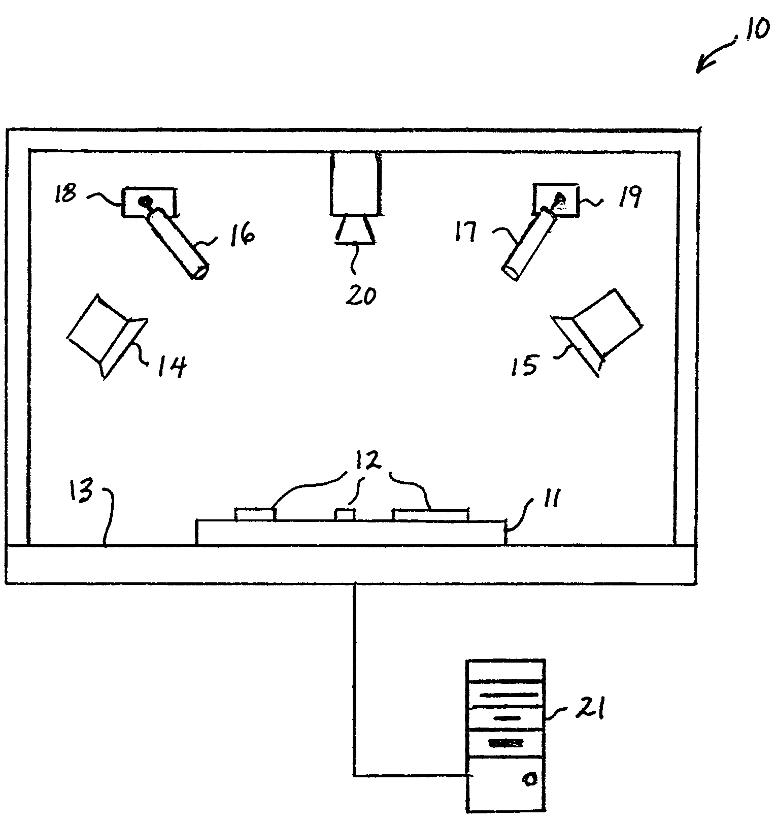
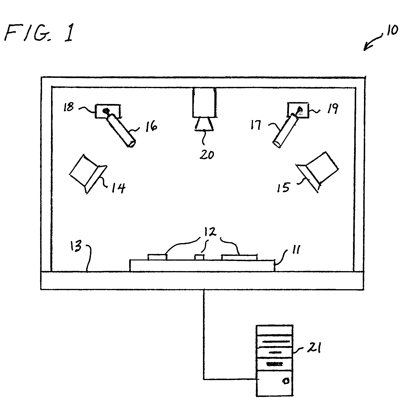
[0015]FIG. 1 is a simplified block diagram of a three-dimensional optical inspection system 10. The present invention utilizes a coherent light source such as a laser light and multi-spectrum visual light together at the same time. A PCB 11 with components 12, or other formations such as solder blocks, on its surface is supported on a support mechanism 13. Two multi-spectrum visual lights 14 and 15 illuminate the PCB from opposite sides. Light 14 may be, for example green, while light 15 is blue. Two coherent red-light lasers 16 and 17 are mounted of...


PUM


Abstract

An optical inspection system and method for inspecting a component on a printed circuit board (PCB) which determines three-dimensional information in a single scan. A first visual light source illuminates the PCB surface and component with a green light while a second visual light source illuminates the PCB and component with a blue light. At least one laser light source simultaneously illuminates the surface of the PCB with a narrow coherent red-light laser beam. The laser light source is mounted off vertical on a movable mount which enables the laser beam to be directed over an area of interest on the surface of the PCB. The system also includes a color scan camera mounted vertically above the PCB. The camera has red, green, and blue channels. The green and blue channels capture an image of the illuminated surface of the PCB which is used by a computer to determine two-dimensional information about the component. The red channel captures a path of the laser beam as it strikes the surface of the PCB and the component. The computer uses the path to determine height information for the component.

Description

BACKGROUND OF THE INVENTION[0001]1. Technical Field of the Invention[0002]The present invention relates to the inspection of structures on an object and, more specifically, to a system and method for optically obtaining three-dimensional information regarding the position of structures on the surface of an object at high speeds.[0003]2. Description of Related Art[0004]Optical inspection devices typically hold an object to be inspected under an overhead camera, and illuminate the object from a single or multiple light sources. Typically, the optical inspection device lights the object from several directions in order to fully illuminate the surface and any objects thereon. The overhead camera captures a two-dimensional gray-scale (black-and-white) image of the object and structures. In a process commonly called convolution, this image is then sent to a computer which compares the image, pixel by pixel, to a stored image of an object with properly positioned structures thereon. If any...

Claims


Application Information

Patent Timeline
Patent Type & Authority Patents(United States)
IPC IPC(8): G06K9/00G06V10/143
CPCG01B11/0608G01N21/956G06K9/2018G06T7/0057G06T2207/30141G06T2207/10024G06T2207/10152G06T7/521G06V10/143
Inventor PATTIKONDA, RAMAKRISHNALIN, YOULING
Owner RUDOLPH TECHNOLOGIES INC
Why Eureka
Try Eureka