Method and system for communicating with a wireless device

a wireless device and wireless communication technology, applied in the field of wireless communication systems and methods, can solve the problems of clock drift between clocks, inability to hard-code identifying information by the manufacturer, and inflexibility and lack of transmitter uniqueness in such a system

Inactive Publication Date: 2006-05-02
AT&T DIGITAL LIFE
View PDF15 Cites 275 Cited by
  • Summary
  • Abstract
  • Description
  • Claims
  • Application Information

AI Technical Summary

Problems solved by technology

Such a level of simplicity is desirable in certain systems, but the flexibility and lack of transmitter uniqueness in such a system is undesirable.
Not every cellular telephone is able to or should be allowed to use the network.
However, such a process can be cumbersome enough for one phone and is especially burdensome when a user needs to register ten, or even one hundred, phones.
The registration for such devices, however, are often hardwired by the manufacturer, the manufacturer burning in the identification information on both the transmitter and the receiver and shipping both transmitter and receiver bundled together.
Such devices possess the ease of use inherent to television remote controls which do not require unique identifiers, but they still suffer from the requirement that identifying information must be hard-coded by the manufacturer.
Another problem that frequently arises in many wireless receiver / transmitter systems is the problem of clock drift between the controller 28 (the receiver) and the wireless control devices 210 (the transmitter).
Typically, these RC oscillators are unstable clocks and require periodic resynchronization to be useful.
What's more, the slight variation in the current drawn from batteries, which many of these wireless control devices use, frequently cause the oscillators to run at slightly skewed rates as compared one to another.
As such, these inexpensive receivers and transmitters which have unstable clocks are prone to drifting out of synchronization over time, causing errors in the data that often cannot be recovered from.
It is clear that such a data read would be erroneous.
For several reasons, this is undesirable generally.
For fairly “inexpensive” devices, such as a light switch or a smoke detector, the grade of synchronized crystals needed to keep the clock drift problem at bay can result in a significant cost of the manufacturing of such “inexpensive” devices going to the cost of the crystals.
Moreover, the data pins on a microprocessor in “inexpensive” devices are often in short supply as product manufacturers squeeze more functionality out of these “inexpensive” devices.

Method used


Image

  • Method and system for communicating with a wireless device
  • Method and system for communicating with a wireless device
  • Method and system for communicating with a wireless device

Examples


third embodiment

[0105]FIG. 9 shows an illustrative system 10 in accordance with the present invention. For purposes of clarity, and not by way of limitation, an illustrative client-server based embodiment of the present invention is herein described. The system 10 illustrates how the wireless system 10 can be incorporated into a larger more encompassing client-server system. Similar references symbols are used throughout the embodiments to show like components.

[0106]System 10 may include an installation 12 and a remote site 14 that may be linked via a communications network 16. In practice, there may be more than one remote site 14 and installation 12, but only one each is shown to avoid over-complicating the drawing. Remote site 14 may be any suitable remote site that may include equipment such as, for example, one or more servers, mainframes, personal computers, or any other suitable computer-based equipment. Remote site 14 may include a network of suitable computers that may be interconnected in...

first embodiment

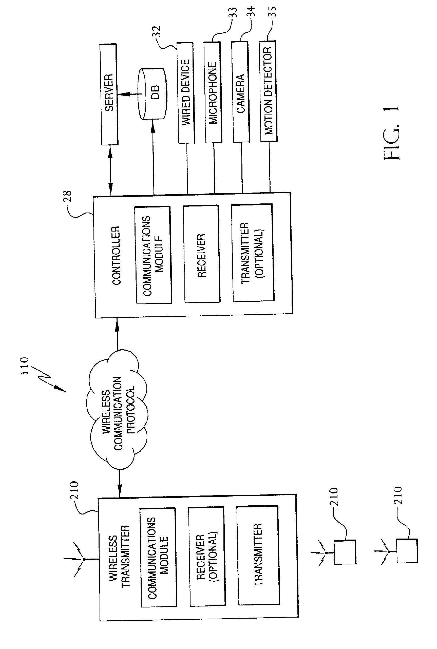
[0117]At least one device 32 may be interfaced with and controlled by each monitoring module 28. Connections between monitoring module 28 and the various devices 32 may be hardwired or wireless such as described in connection with FIGS. 1-4. Devices 32 may encompass any suitable device capable of being controlled or mediated by an external controller. Such devices may include, but are not limited to, a camera 34, a radio 36, a wireless smoke or fire detector 38, a wireless contact sensor 40, and a wireless light switch 41. Although not illustrated, other suitable devices may include, for example, various audio input and output devices, various visual displays, washers / driers, microwave ovens, cooking ranges, car alarms, plant watering devices, sprinkler, thermostats, carbon monoxide sensors, humidistats, rain gauges, video cassette recorders, radio tuners, or any other suitable device and the like.

[0118]One or more notification devices, such as pager 43, may also be incorporated int...


PUM


Abstract

A method, system, transmitter, receiver and protocol are disclosed for communicating with wireless receivers. The invention includes providing a controller having a discovery mode and an operating mode, in the discovery mode the controller is capable of registering wireless devices, in the operating mode the controller is capable of receiving transmissions from a wireless device that has been registered. A wireless transmitter is provided which is capable of communicating wirelessly with the controller. The wireless device has an actuator for initiating at least one transmission of registration data. When the controller is placed into the discovery mode, and the actuator of the wireless device is actuated to wirelessly transmit the registration data from the wireless device to the controller, whereby the wireless device is registered with the controller. The wireless data contains data that allows the controller to interface with the wireless device.

Description

[0001]This application claims benefit of provisional No. 60 / 253,359 Nov. 28, 2000 which claims benefit of provisional No. 60 / 253,358 Nov. 28, 2000 and claims benefit of provisional No. 60 / 253,464 Nov. 28, 2000.BACKGROUND OF THE INVENTION[0002]The invention relates to systems and methods for communicating with wireless devices.[0003]Many systems today use wireless devices to transmit information. Television remote controls transmit information to a television via infrared signals. Cellular phones use radio frequencies to send and receive information. Wireless systems for monitoring inmates in a location employ the tight coupling of a transmitter on an inmate to the center point receiver in order to alert a “break out” condition when the inmate wanders outside the allowed radius of the receiver. In order for any transmitter in such systems to communicate with it's corresponding receiver, that receiver needs to know intimate knowledge about the types of transmitters attempting the comm...

Claims


Application Information

Patent Timeline
Patent Type & Authority Patents(United States)
IPC IPC(8): H04M1/66H04L12/56H04L29/06
CPCH04L63/08H04L63/123H04W8/005H04W60/00H04W12/06H04W12/062
Inventor REZVANI, BABAKCHEN, JACK L.LAIBOWITZ, MATHEW JOELKALIN, EDWARD BRIANGHALEBI, MEHRDAD
Owner AT&T DIGITAL LIFE
Why Eureka
Try Eureka