Combined aftercooler system with shared fans

a technology of aftercooler and shared fans, which is applied in the direction of engine cooling apparatus, combustion engines, machines/engines, etc., can solve the problems of undesirable addition of fans and large heat exchangers, and achieve the effect of simplifying efficient locomotive cooling systems and significantly reducing the intake air temperature of supercharged diesel engines

Inactive Publication Date: 2006-05-09
ELECTRO-MOTIVE DIESEL
View PDF6 Cites 30 Cited by
  • Summary
  • Abstract
  • Description
  • Claims
  • Application Information

AI Technical Summary

Benefits of technology

[0006]The present invention provides simplified efficient locomotive cooling systems for significantly reducing supercharged diesel engine intake air temperatures.

Problems solved by technology

However, due to cost and space limitations, on locomotives, additional fans and larger heat exchangers are undesirable.

Method used


Image

  • Combined aftercooler system with shared fans
  • Combined aftercooler system with shared fans
  • Combined aftercooler system with shared fans

Examples


Embodiment Construction

[0022]In the following description, like numerals indicate like parts or features throughout the various figures of the drawings.

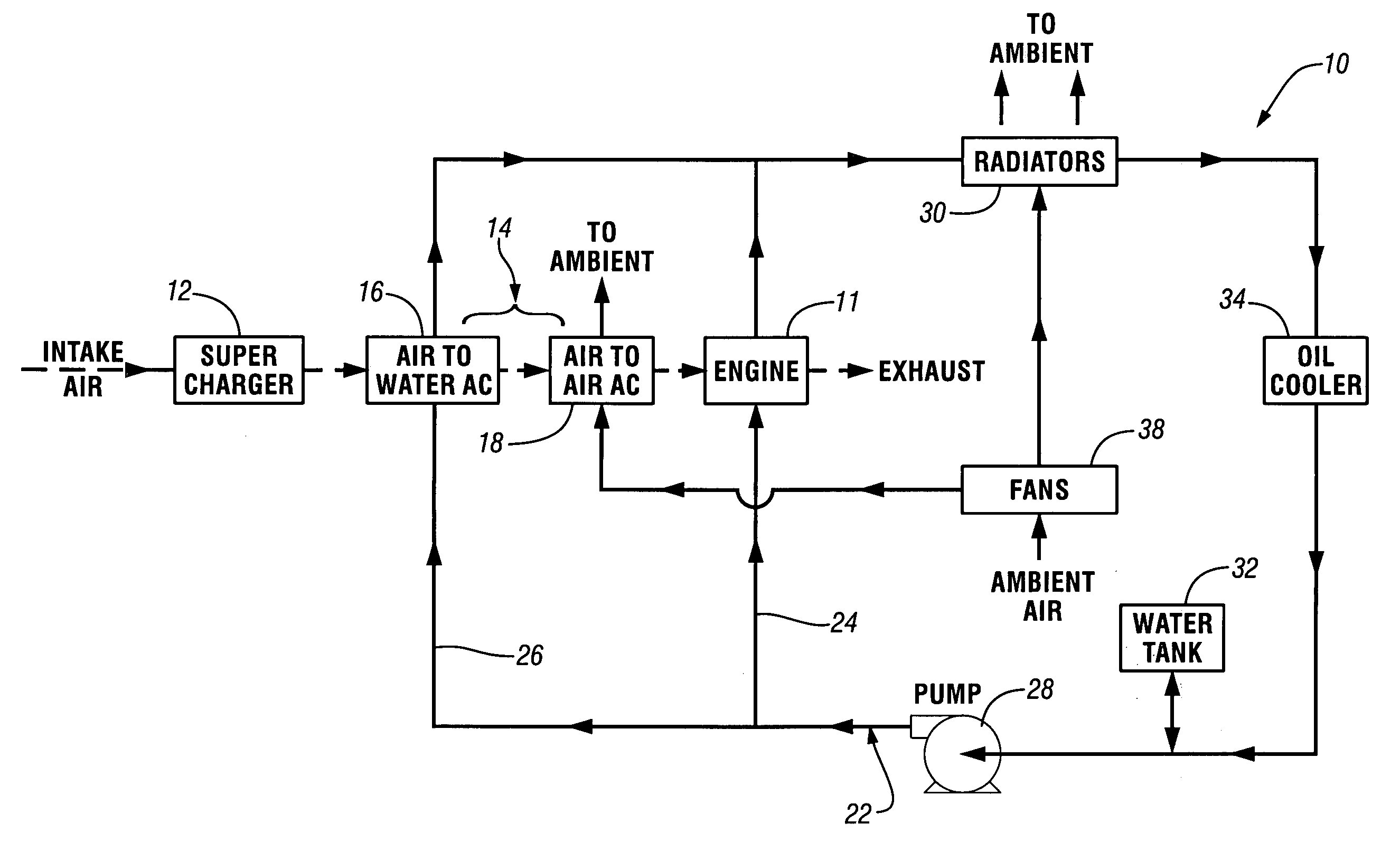
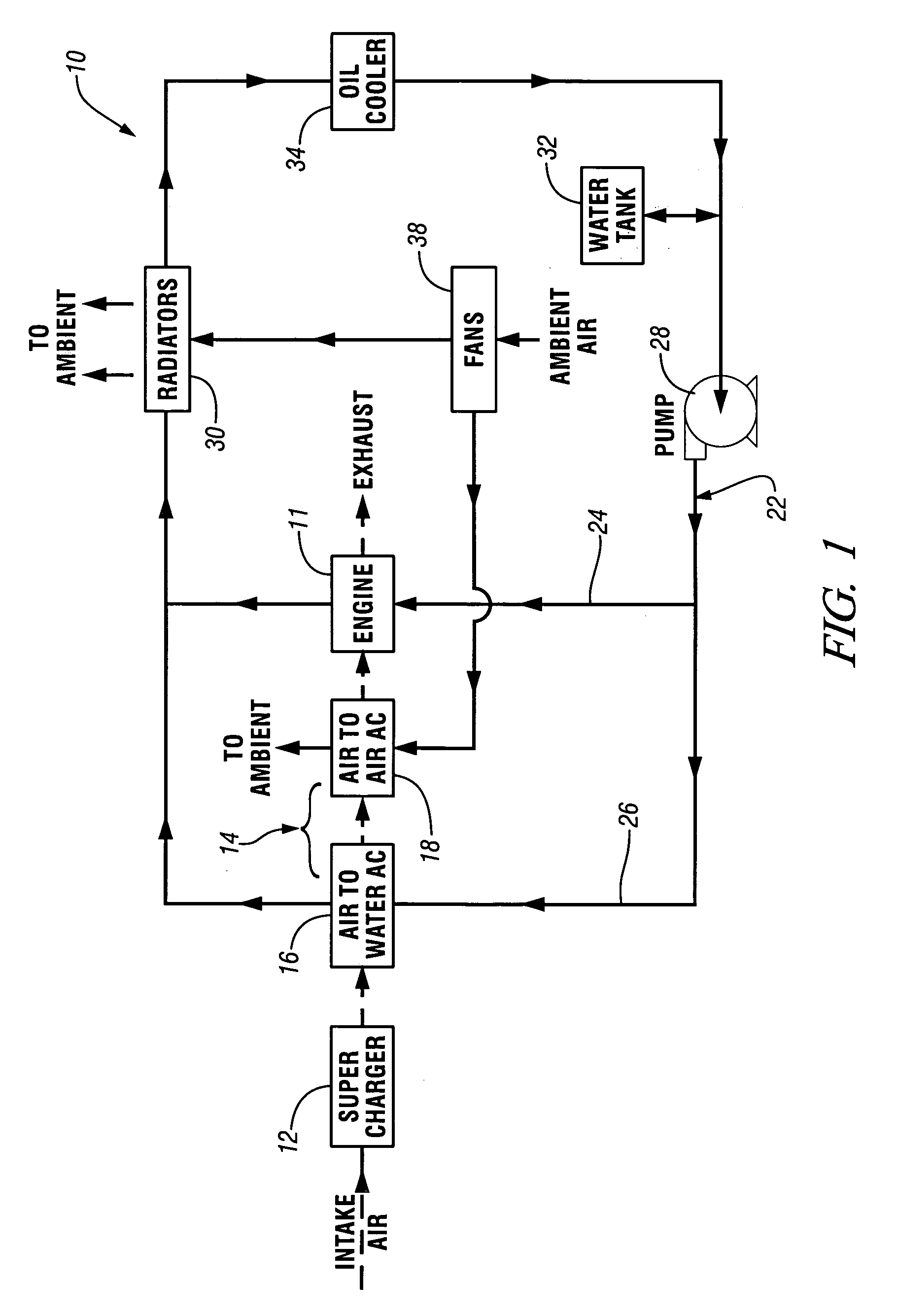
[0023]Referring first to FIG. 1 of the drawings in detail, numeral 10 generally indicates an engine cooling system for a supercharged internal combustion diesel locomotive engine 11. The engine 11 receives compressed intake air from a supercharger 12 through an intake air cooling subsystem 14 including intake air sides of an air-to-water aftercooler 16 and an air-to-air aftercooler 18. The aftercoolers 16, 18 are positioned with their intake air sides in series in the air stream from the supercharger 12 to the engine 11.

[0024]The cooling system 10 also includes a liquid cooling subsystem 22 having first and second overlapping liquid cooling loops 24, 26. The first liquid cooling loop 24 includes a coolant pump 28, the diesel engine 11, the water sides of one or more water radiators 30, a water (coolant) tank 32 and an optional oil cooler 34. The second liq...


PUM


Abstract

A cooling system including an intake air cooling subsystem and a liquid cooling subsystem for controlling intake air temperatures in a supercharged internal combustion diesel locomotive engine. The intake air cooling subsystem includes an air-to-water aftercooler and an air-to-air aftercooler having intake air sides connected to receive intake air flow in series between a supercharger and an engine. The liquid cooling subsystem includes at least one liquid cooling loop having a pump, a radiator and a water coolant side of the air-to-water aftercooler. At least one shared fan circulates air flow to the cooling air sides of the air-to-air aftercooler and the radiator. An optional air distribution control selectively directs circulated air flow between the air-to-air aftercooler, the radiator and other optional components of the cooling system.

Description

TECHNICAL FIELD[0001]This invention relates to diesel electric locomotives and, more particularly, to cooling systems for cooling engine coolant and intake air in supercharged diesel engines.BACKGROUND OF THE INVENTION[0002]Diesel locomotive engines may utilize one or more superchargers to increase engine power by compressing ambient air to reduce its volume and increase its density. As the intake air is compressed by the supercharger, the air is heated to high temperatures. In order to reduce the temperature of the intake air and increase its density, an aftercooler is positioned downstream from the supercharger.[0003]Tier 2 emission guidelines promulgated by the Environmental Protection Agency (EPA) set forth stringent emission standards for diesel locomotive engines. A preferred method of complying with the Tier 2 emission guidelines is to reduce intake air temperatures and thereby reduce the formation of NOx and other emissions during combustion.[0004]Conventional locomotive coo...

Claims


Application Information

Patent Timeline
Patent Type & Authority Patents(United States)
IPC IPC(8): F02B29/04
CPCF01P7/165F02B29/0412F02B29/0431F02B29/0443F01P11/029F01P2005/105F01P2060/02Y02T10/146F01P2060/04Y02T10/12
Inventor UZKAN, TEOMANCRYER, III, EDWARD J.
Owner ELECTRO-MOTIVE DIESEL
Why Eureka
Try Eureka