Method and device for exhaust recycling and supercharged diesel engine

a diesel engine and exhaust technology, applied in the direction of machines/engines, mechanical equipment, combustion-air/fuel-air treatment, etc., can solve the problems of ineffective technology, inapplicability of otto engine solutions to diesel engines, and combustion in diesel engines normally occurs with excess air, so as to reduce the pumping effect and simple construction

Inactive Publication Date: 2006-05-09
SCANIA CV AB
View PDF5 Cites 16 Cited by
  • Summary
  • Abstract
  • Description
  • Claims
  • Application Information

AI Technical Summary

Benefits of technology

[0007]It is an aim of this invention to provide a solution to or a reduction of the problems of the prior art. A main aim is thus to provide a simpler and more effective transfer of EGR gases in a combustion engine.
[0009]The invention makes it possible to minimise flow resistance losses since valve blades and similar control devices become unnecessary. Further, all intake air may be used for controlled EGR pumping in the venturi since no by-pass channel needs to be arranged. This gives great advantages since the pressure drop over the venturi device may be held at a minimum. Altogether the result will be enhanced engine performance.
[0010]By making it possible to adjust flow actuation by adjusting at least a portion of the wall, so that the amount of air and recycled gasses as well as time for recycling may be optimized. This adjustment is simple to obtain and results in effective variation, whereby EGR recycling simply can be optimized for the prevailing operation. The adjustment is preferably controlled by a suitable sequence being programmed in the usual engine control computer, said sequence preferably using data being supplied by the ordinary parameter sensors of the engine.
[0013]It is preferred that the venturi wall has a sideward recess wherein the adjustable wall portion is variably insertable. This way achieves a simple construction, making it possible for the venturi to be in principle out of function with a resulting minimal pressure drop when the adjustable wall portion is entirely inserted into the recess.
[0016]If the opening of the EGR channel in the venturi is directed essentially in the flow direction of the intake air, it is achieved that pressure pulses in the EGR channel will not reduce the pumping effect.
[0017]It is preferred that the section of the venturi is essentially rectangular with adjustable height. This geometry gives simple construction and adjustability.

Problems solved by technology

In diesel engines, on the other hand, this technique has not been employed to such a great extent depending i.a. on the fact that there are particular problems associated with these engines, making Otto engine solution not directly applicable in diesel engines.
One of these particular problems is that the combustion in diesel engines normally occurs with excess air.
This problem is accentuated in case of an engine of the super-charged type, because in that case the pressure in the intake system of the engine is greater than the pressure in the exhaust gas system during a great part of the operating range.
A drawback with these solutions is the need of the extra super-charging device or any other pressure increasing means, which makes these solutions both costly and bulky.
A major problem, which the devices according to these documents suffer from, is that flow resistance losses occur in the intake channel because of the configuration of the devices.
As an example, the use of a valve blade in a by-pass channel brings along a pressure drop with resulting power waste for the engine.

Method used


Image

  • Method and device for exhaust recycling and supercharged diesel engine
  • Method and device for exhaust recycling and supercharged diesel engine
  • Method and device for exhaust recycling and supercharged diesel engine

Examples


Embodiment Construction

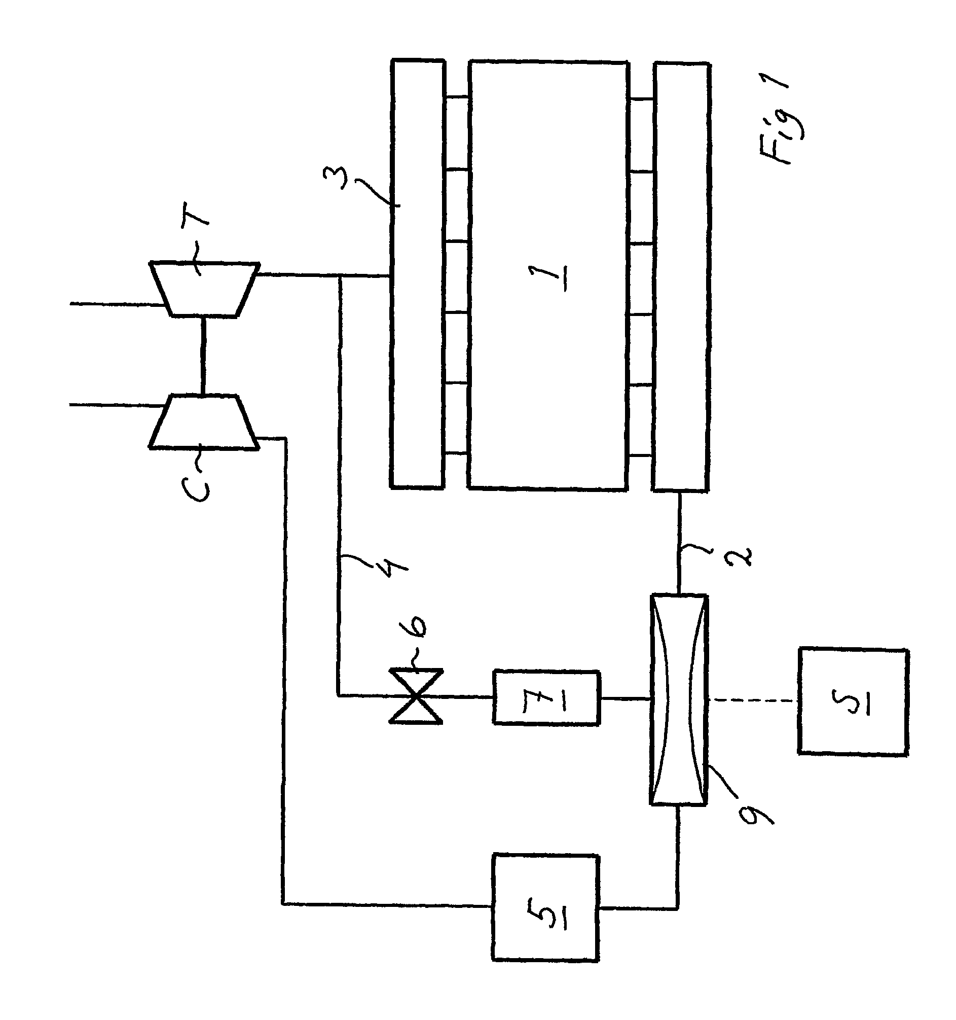
[0023]FIG. 1 shows diagrammatically a combustion engine 1 of the piston engine type with cylinders arranged in a straight inline cylinder block. The engine is a four-stroke diesel engine adapted for a heavy vehicle such as a truck or a bus. Each cylinder is in its respective cylinder head in a conventional manner provided with at least one intake valve for supply of combustion air and at least one exhaust valve for discharge of exhaust gases from the combustion. An intake channel 2 leads the intake air to the cylinders whereas an exhaust collector 3 leads the exhaust gases from the cylinders to the turbine T and subsequently to the exhaust pipe.

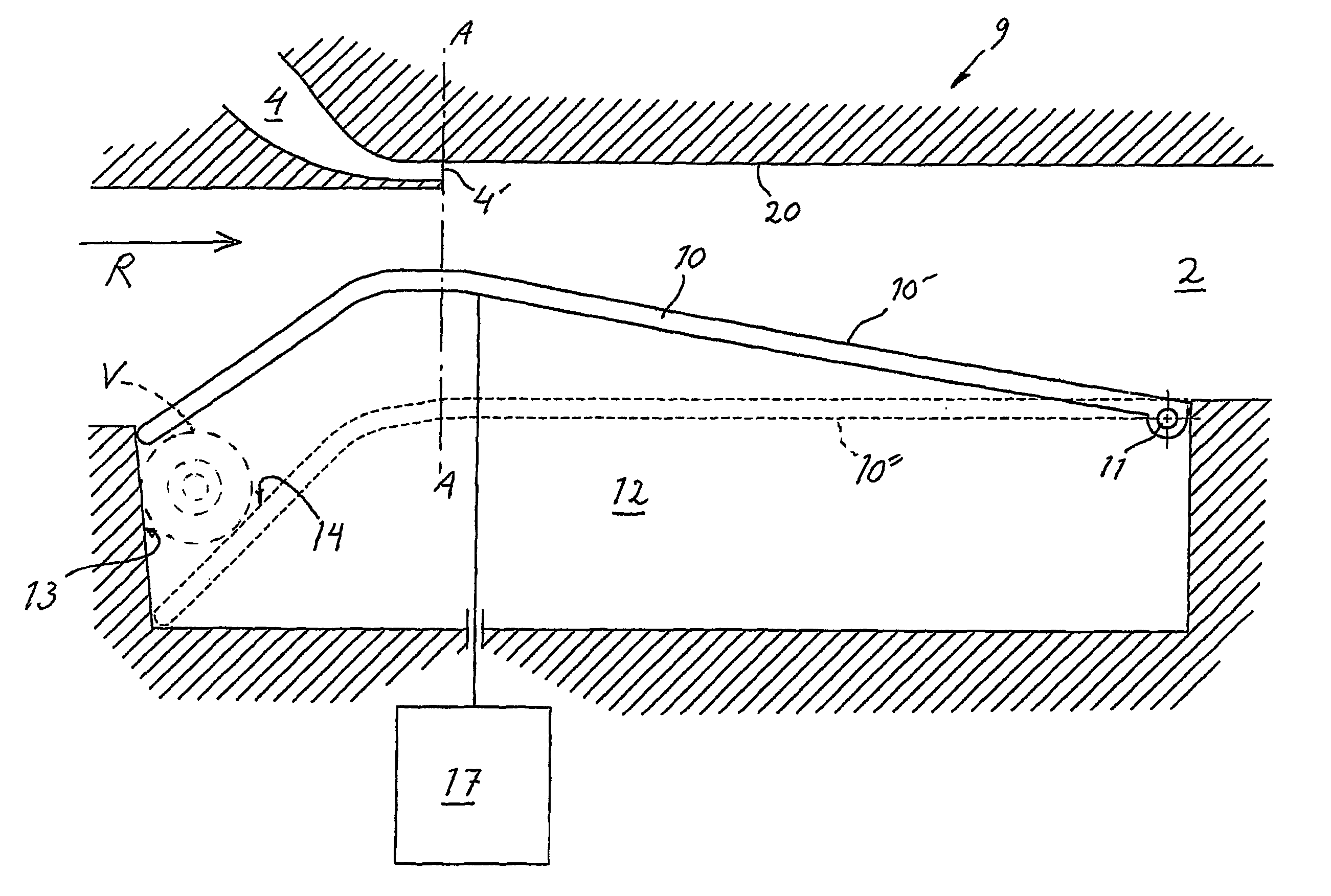
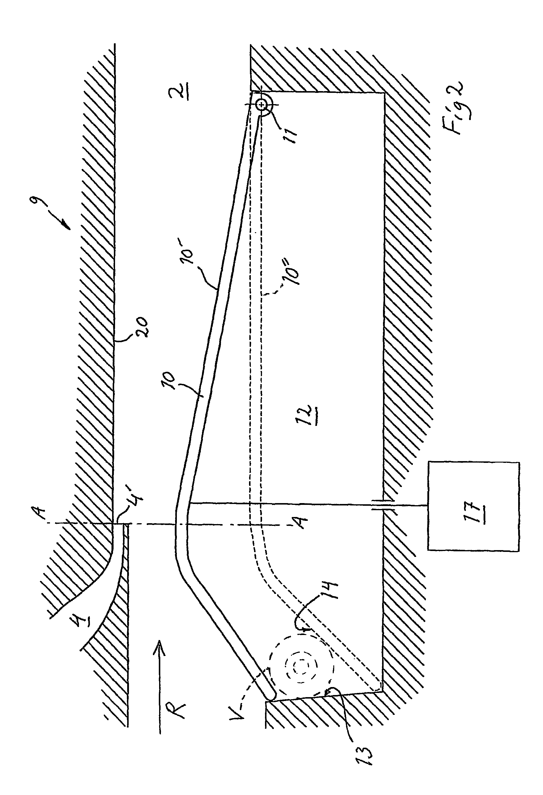
[0024]Further, a transfer channel 4 is arranged for recycling EGR gases from the exhaust side of the cylinders to their intake side. The transfer channel 4 debouches in the intake channel 2 after a charging air cooler 5 and before a manifold to the cylinders. An EGR control valve 6 is positioned in the transfer channel whereby the transfer ma...


PUM


Abstract

A method and a device for exhaust gas recycling (EGR) in a combustion engine (1), wherein EGR gases are led into a section of the intake channel where a venturi (9) is arranged for modifying the flow of the intake air, and where a reduced pressure prevails because of modified flow, wherein at least a portion of the wall (10) of the venturi (9) is adjustable for varying the cross section of the venture and thereby for desired adjustment to prevailing operational conditions.

Description

FIELD OF THE INVENTION[0001]This invention concerns a method and a device for adjusting the flow of exhaust gas recycling gasses and intake air in a venturi section of an intake channel of an engine. It also concerns a supercharged engine including such a device.DESCRIPTION OF PRIOR ART[0002]In turbo-supercharged diesel engines it is previously known to recycle exhaust gases to the engine inlet in order to reduce contents of nitrous oxides in the exhaust gases. Hereby the recycled exhaust gases function as to lower the combustion temperature resulting in that a smaller amount of the nitrogen in the inlet air can be converted into nitrogen oxides. This process, usually called EGR (exhaust gas recirculation) has often been used in Otto engines as a relatively simple way of reducing the contents of harmful exhaust gas emissions. In diesel engines, on the other hand, this technique has not been employed to such a great extent depending i.a. on the fact that there are particular problems...

Claims


Application Information

Patent Timeline
Patent Type & Authority Patents(United States)
IPC IPC(8): F02M25/07F02D9/02F02D9/10F02D9/18F02D21/08
CPCF02D9/18F02D21/08F02M35/10222F02M25/0722F02M25/0707Y02T10/146F02M25/0727Y02T10/121F02M26/05F02M26/19F02M26/23Y02T10/12
Inventor SPONTON, OVE
Owner SCANIA CV AB
Why Eureka
Try Eureka