Turbocharger with a double-vane nozzle system

Inactive Publication Date: 2014-03-27
WUXI KAIDI SUPERCHARGER ACCESSORIES
View PDF32 Cites 4 Cited by
  • Summary
  • Abstract
  • Description
  • Claims
  • Application Information

AI Technical Summary

Benefits of technology

The present invention provides a turbocharger with a dual-vane nozzle system that reduces cross flow losses, keeps the turbine operating in the high-efficiency zone, and reduces flow resistance losses. The new blades along the flow path of the nozzle reduce the section area of the passage, while the fixed vanes partition the nozzle into two air passages. The blade design allows for adjustment of the area of the nozzle outlet to meet varying engine demands. These technical effects enable improved performance and efficiency of the turbocharger.

Problems solved by technology

Waste gas discharged from an engine can work for the turbine in the supercharger, but it can only operate within a narrow high-efficiency zone.
However, the aerodynamic performance is not good.
It also reduces the heat efficiency of the turbine decreasing.

Method used


Image

  • Turbocharger with a double-vane nozzle system
  • Turbocharger with a double-vane nozzle system
  • Turbocharger with a double-vane nozzle system

Examples


embodiment i

[0026]It is given that there are eight fixed vanes 8 and eight moving blades 7, and the intake angle of the blade, i.e. the blade incidence is 21 degree.

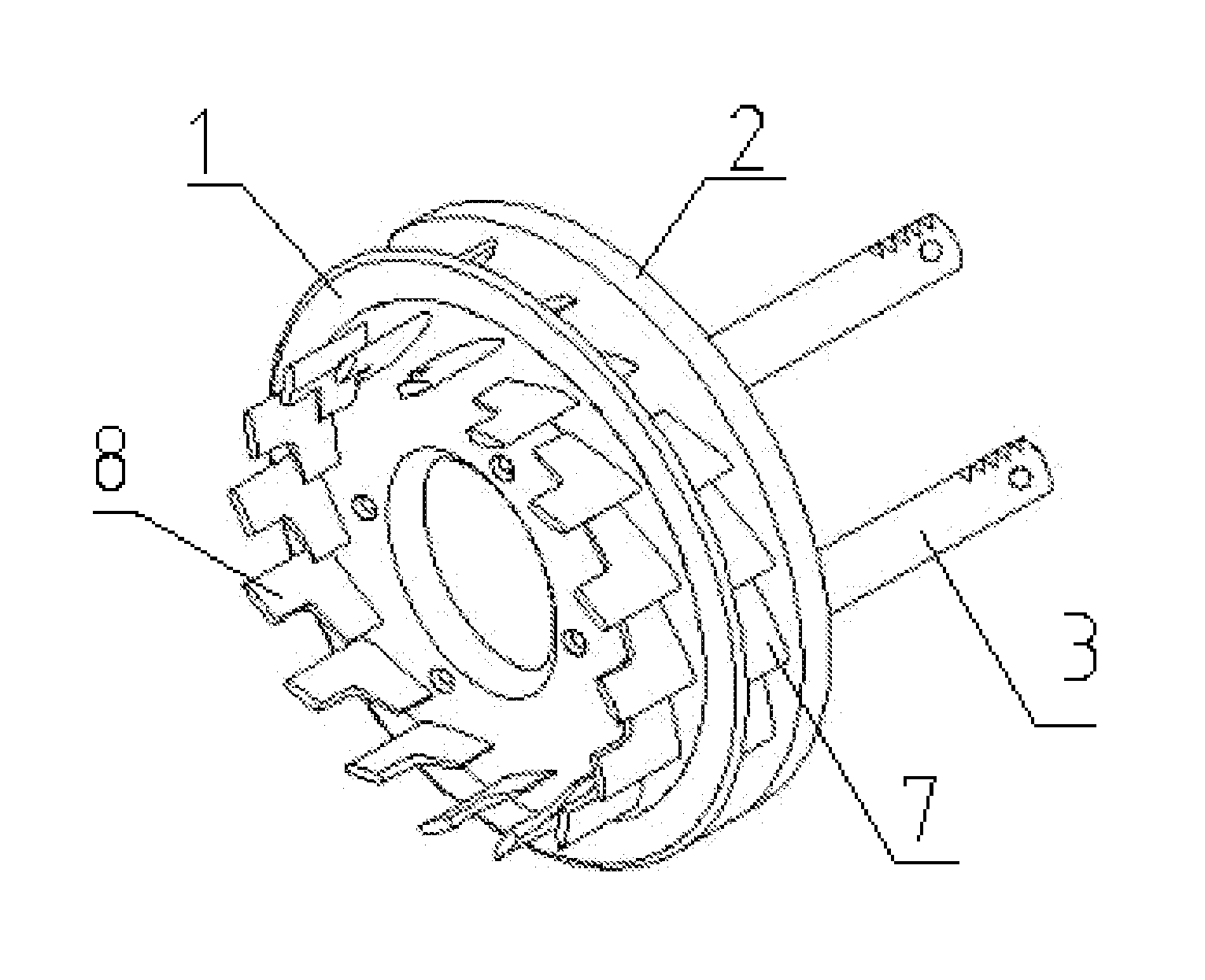
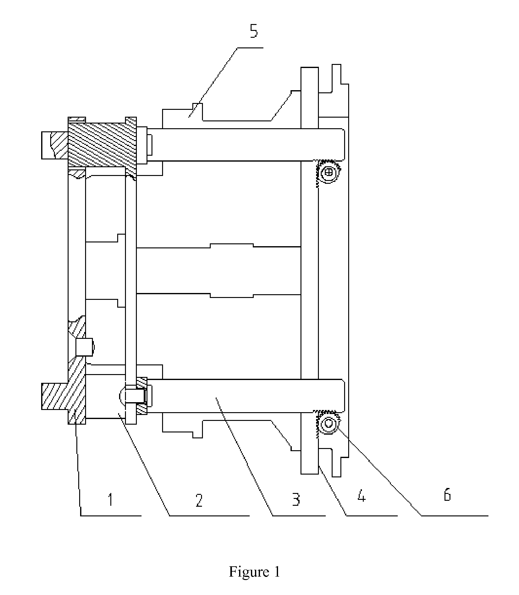
[0027]As shown in FIGS. 1, 4, and 10, a group of airfoil fixed vane 8 are provided on the front end face of the fixed nozzle ring 1, blade-shaped holes 9 are arranged between the fixed vanes 8, the fixed nozzle ring 1 is provided with a center hole at the center and sheathed around the circumference of the middle-housing 5 and fixed to the middle-housing 5 via screws, a linearly moving nozzle disk 2 is mounted on the rear end of the fixed nozzle ring 1.

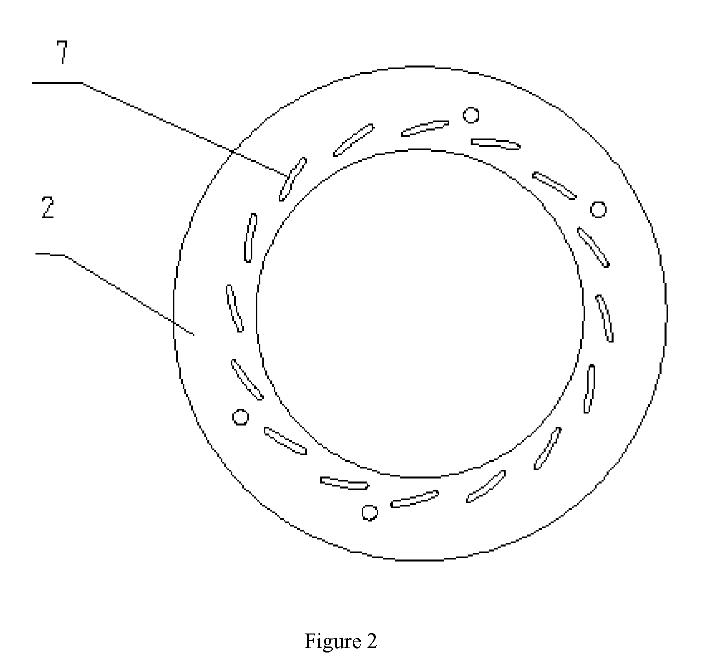
[0028]As shown in FIGS. 2 and 10, a group of moving blades 7 are provided on the front end face of the linearly moving nozzle disk 2, the shape of the moving blade 7 is consistent with that of the blade-shaped hole 9, the moving blades 7 are moveably inserted into the blade-shaped holes 9.

[0029]As shown as in FIGS. 1, 5, 6, and 10, two rocker arm rods 3 are fixed to the rear end face ...

embodiment ii

[0035]The difference between the present embodiment II and the embodiment I is that the driving device pushing the rack upward and downward is a solenoid valve.


PUM


Abstract

Disclosed is a turbocharger with a dual-blade nozzle system, comprising a turbine housing, a fixed nozzle ring (1), a linearly moving nozzle disk (2), a mid-housing (5), a rack (4), rocker arm rods (3), and a gear (6), wherein airfoil-shaped fixed blades (8) are provided on the front end face of the fixed nozzle ring (1), with blade-type holes (9) provided between the fixed blades (8), and the fixed nozzle ring (1) is sheathed around the outside of the mid-housing (5) and fixed to the mid-housing (5) via screws; the linearly moving nozzle disk (2) is provided on the rear end of the fixed nozzle ring (1), a group of moving blades (7) is provided on the front end face of the linearly moving nozzle disk (2), the moving blades (7) are movably inserted into the blade-type holes (9), the rear end face of the linearly moving nozzle disk (2) is fixedly connected to two rocker arm rods (3), with the rocker arm rods (3) inserted into the mid-housing (5) and engaged with the rack (4) via the gear (6). The provision of an additional blade along a nozzle flow passage in the turbocharger with the dual-blade nozzle system can not only reduce the cross-sectional area of the passage, but also separate the original nozzle into two gas passages to reduce the loss of gas flow due to transverse flow; in addition, the gas flow can flow at an optimum gas flow angle according to the original design, so that the turbine can keep working in the high efficiency region.

Description

FIELD OF TECHNOLOGY[0001]The present invention relates to a turbocharger with a double-vane nozzle system, belonging to the field of an automobile device.BACKGROUND OF TECHNOLOGY[0002]Waste gas discharged from an engine can work for the turbine in the supercharger, but it can only operate within a narrow high-efficiency zone. Even through the design point of the vehicular supercharger is set within a range of 50-70%, when the engine is operating at full load, the over-speed of the supercharger occurs. Therefore, an exhaust bypass valve mechanism is arranged on the supercharger in order to improve the reliability while a portion of available energy of gas is wasted.[0003]An effective method to improve the aerodynamic performance of the turbine is to employ a variable nozzle structure, and it is also generally acknowledged and practiced by each of the world-wide supercharger manufacturers. At present, there are three different solutions:The Chinese patent application No. 200710152744....

Claims


Application Information

Patent Timeline
IPC IPC(8): F04D17/10
CPCF04D17/10F02B37/24F01D17/165F05D2220/40Y02T10/12
Inventor SHI, YONGQIANG
Owner WUXI KAIDI SUPERCHARGER ACCESSORIES
Why Eureka
Try Eureka