Ejector-based cryogenic refrigeration system for cold energy recovery

a cryogenic refrigeration and ejector technology, applied in the field of cryogenic refrigeration systems, can solve the problems of compressors that consume a large amount of power, cannot be cooled by being immersed in liquid helium, and low system efficiency, so as to reduce the gas flowing, improve the utilization efficiency of devices, and reduce the cost

Active Publication Date: 2021-01-28
XI AN JIAOTONG UNIV
View PDF0 Cites 1 Cited by
  • Summary
  • Abstract
  • Description
  • Claims
  • Application Information

AI Technical Summary

Benefits of technology

[0019]The cryogenic refrigerator and the cryogenic helium cooling loop share a helium compressor, which improves the utilization efficiency of the device and reduces the cost. The ejector allows a part of fluids to circulate in the cryogenic loop, so as to maintain a required cryogenic condition, recover the pressure of the fluids, reduce the gas flowing though the compressor loop, and reduce the power consumption of the compressor. In addition, the loss caused by heat exchange and flow resistance is reduced due to the use of the ejector, so that the heat exchange efficiency is improved. Besides, the cryogenic refrigerator and the end to be cooled are separated to effectively reduce the influence of the vibration of the refrigerator on the end to be cooled, so as to ensure the balance of the end to be cooled.

Problems solved by technology

However, some moving devices, such as generators with rotors, cannot be cooled by being immersed in the liquid helium.
However, in the circulating process, there is much helium gas flowing through the compressor, resulting in that the compressor consumes a large power, which causes a low efficiency of the system.
In addition, there is a large flow resistance when fluids flow through the heat regenerator.
Besides, if the low temperature is directly provided by the cold head of the cryogenic refrigerator, the vibration of the refrigerator may influence the end to be cooled.

Method used


Image

  • Ejector-based cryogenic refrigeration system for cold energy recovery
  • Ejector-based cryogenic refrigeration system for cold energy recovery
  • Ejector-based cryogenic refrigeration system for cold energy recovery

Examples


embodiment 1

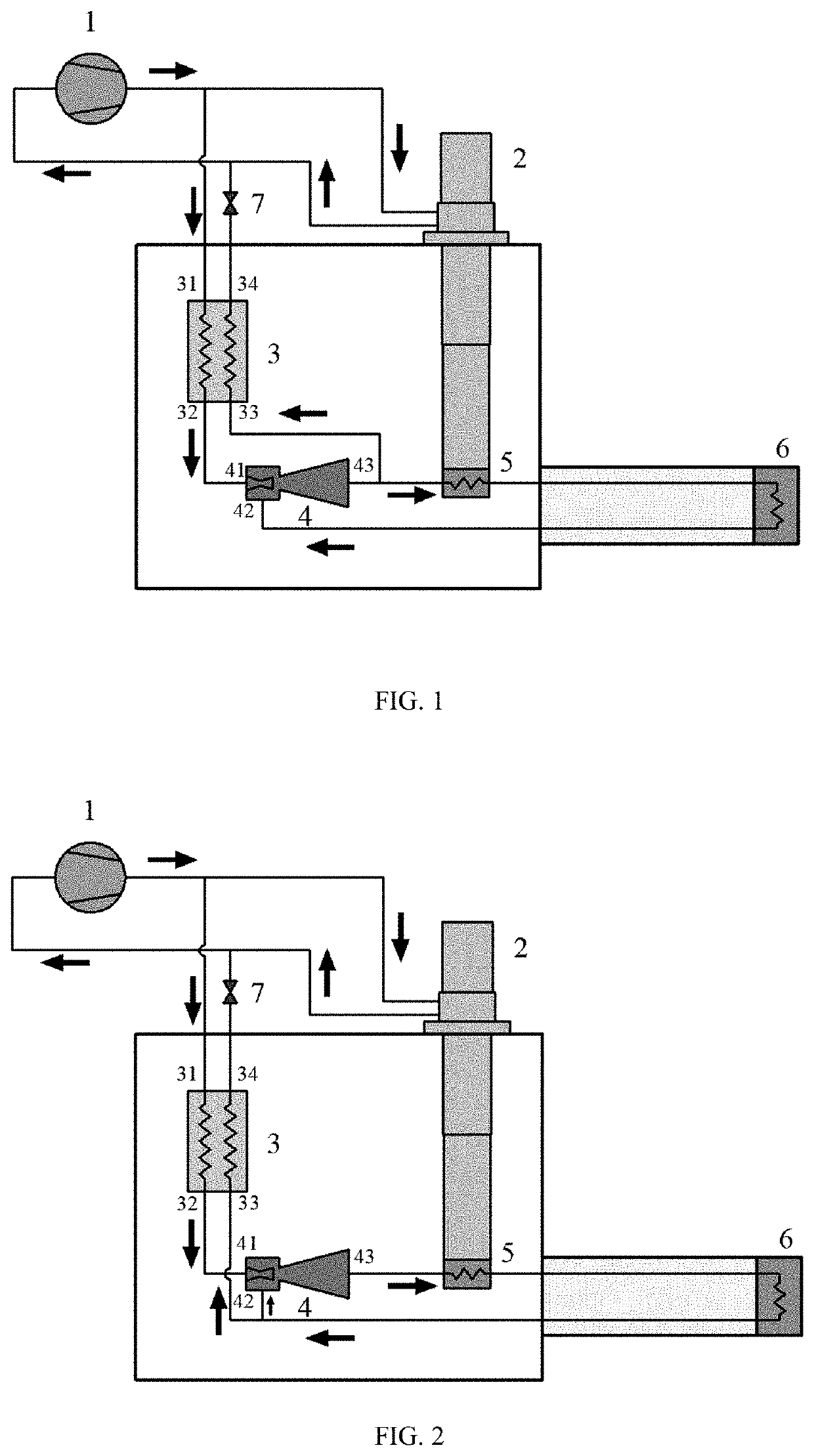
[0028]As shown in FIG. 1, this embodiment illustrates an ejector-based cryogenic refrigerator for cold energy recovery, including a helium compressor 1. A first outlet of the helium compressor 1 is connected to an inlet of a cryogenic refrigerator 2; an outlet of the cryogenic refrigerator 2 is communicated with the inlet of the cryogenic refrigerator 2 and is connected to an inlet of the helium compressor 1, so that a cold head 5 of the cryogenic refrigerator 2 has a temperature of 20 K.

[0029]A second outlet of the helium compressor 1 is connected to a hot fluid inlet 31 of a regenerator 3. A hot fluid outlet 32 of the regenerator 3 is connected to a primary inlet 41 of an ejector 4. An outlet 43 of the ejector 4 has two ports. A first port of the outlet 43 of the ejector 4 is connected to an inlet of a cold head 5 of the cryogenic refrigerator 2. An outlet of the cold head 5 of the cryogenic refrigerator 2 is connected to an inlet of an end 6 to be cooled. An outlet of the end 6 t...

embodiment 2

[0031]As shown in FIG. 2, this embodiment illustrates an ejector-based cryogenic refrigeration system for cold energy recovery, including a helium compressor 1. A first outlet of the helium compressor 1 is connected to an inlet of a cryogenic refrigerator 2. An outlet of the cryogenic refrigerator 2 is communicated with the inlet of the cryogenic refrigerator 2 and is connected to an inlet of the helium compressor 1, so that a cold head of the cryogenic refrigerator 2 has a temperature of 20 K.

[0032]A second outlet of the helium compressor 1 is connected to a hot fluid inlet 31 of the regenerator 3. A hot fluid outlet 32 of the regenerator 3 is connected to a primary inlet 41 of the ejector 4. An outlet 43 of the ejector 4 is connected to an inlet of the cold head 5 of the cryogenic refrigerator 2. An outlet of the cold head 5 of the cryogenic refrigerator 2 is connected to an inlet of an end 6 to be cooled. A first outlet of the end 6 to be cooled is connected to a secondary inlet ...

embodiments 3

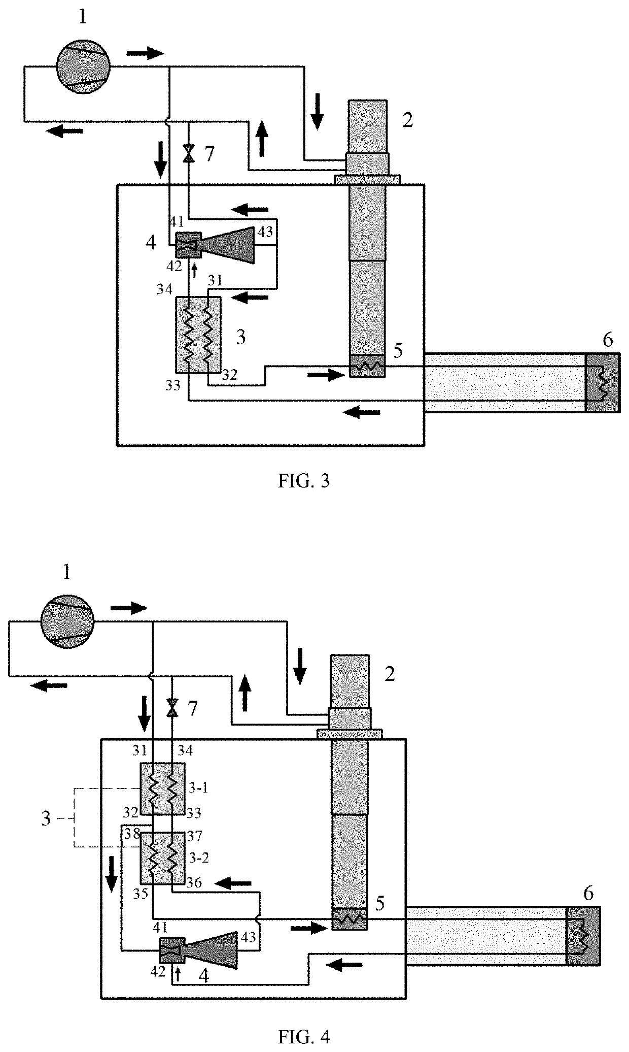
[0034]As shown in FIG. 3, illustrated is an ejector-based cryogenic refrigeration system for cold energy recovery, including a helium compressor 1. A first outlet of the helium compressor 1 is connected to an inlet of a cryogenic refrigerator 2; an outlet of the cryogenic refrigerator 2 is communicated with the inlet of the cryogenic refrigerator 2 and is connected to an inlet of the helium compressor 1, so that a cold head of the cryogenic refrigerator 2 has a temperature of 20 K.

[0035]A second outlet of the helium compressor 1 is connected to a primary inlet 41 of the ejector 4. An outlet 43 of the ejector 4 has two ports. A first port of an outlet 43 of the ejector 4 is connected to a hot fluid inlet 31 of a regenerator 3. A hot fluid outlet 32 of the regenerator 3 is connected to an inlet of the cold head 5 of the cryogenic refrigerator 2. An outlet of the cold head 5 of the cryogenic refrigerator is connected to an inlet of the end 6 to be cooled. An outlet of the end 6 to be c...


PUM


Abstract

An ejector-based cryogenic refrigeration system for cold energy recovery includes a first cryogenic refrigeration loop connected by a helium compressor and a cryogenic refrigerator and a second cryogenic refrigeration loop connected by the helium compressor, a regenerator, an ejector, a cold head of the cryogenic refrigerator, an end to be cooled and a pressure regulating valve. The cryogenic refrigerator is separated from the end to be cooled. The cryogenic refrigerator and the cryogenic helium cooling loop share a helium compressor, which improves the utilization efficiency of the device and reduces the cost. The ejector allows a part of fluids to circulate in the cryogenic loop, so as to maintain a required cryogenic condition, recover the pressure of the fluids, reduce the gas flowing though the compressor loop, and thus reduce the power consumption of the compressor.

Description

CROSS-REFERENCE TO RELATED APPLICATION[0001]This application claims the benefit of priority from Chinese Patent Application No. 201910669449.X, filed on Jul. 24, 2019. The content of the aforementioned application, including any intervening amendments thereto, is incorporated herein by reference in its entirety.TECHNICAL FIELD[0002]This application relates to a cryogenic refrigeration system, and more particularly to an ejector-based cryogenic refrigeration system for cold energy recovery.BACKGROUND OF THE DISCLOSURE[0003]Superconductivity means that resistance of certain metals, alloys or compounds decreases to almost zero when they are at a specific temperature close to absolute zero. Due to the zero resistance and perfect diamagnetism, superconducting materials are widely used in electronic applications such as superconducting microwave devices, superconducting computers and superconducting antennas, etc.; large current applications such as superconducting power generation, super...

Claims


Application Information

Patent Timeline
Patent Type & Authority Applications(United States)
IPC IPC(8): F25B9/00F25B9/14
CPCF25B9/002F25B2341/0012F25B9/14F25D31/00F25B9/00F25B40/06F25B9/08F25D19/006F25B40/00F25B41/00
Inventor LI, CUIZHUANG, YUHANCHENG, YIWEISHI, JIAMINLI, YANZHONG
Owner XI AN JIAOTONG UNIV
Why Eureka
Try Eureka