Heat transfer device

a technology of heat transfer device and heat transfer plate, which is applied in indirect heat exchangers, lighting and heating apparatuses, laminated elements, etc., can solve the problems of material deformation and high material tension

Inactive Publication Date: 2006-05-09
ROBERT BOSCH GMBH
View PDF40 Cites 15 Cited by
  • Summary
  • Abstract
  • Description
  • Claims
  • Application Information

AI Technical Summary

Benefits of technology

[0010]In contrast, the object of the invention is to propose an apparatus for transferring heat that realizes a comparably large heat-transferring surface within a small volume, hereby guaranteeing uninterrupted operation even when the pressure differential between the fluids is great.
[0011]Accordingly, an apparatus according to the invention is unusual in that the inlet and / or exit area comprises at least one support element. According to the invention, this greatly reduces the resultant exposed cross section and, in particular, the bending moment occurring in the inlet or exit area. This ensures that the area acted upon by pressure, in particular on the side operated using comparably low pressure, is supported, thereby preventing a disadvantageous deformation of the plate.
[0012]Moreover, by arranging the support elements in advantageous fashion, a support element according to the invention provided on each plate can transmit corresponding pressure forces from plate to plate until a relatively massive cover plate absorbs the pressure forces, if necessary, effectively preventing a deformation of the plates or failure of the entire component.

Problems solved by technology

The large surface area acted upon by pressure in the region of the exposed cross section causes high material tensions to occur.
This can result in material deformations, e.g., flowing or failure of the component.

Method used


Image

  • Heat transfer device
  • Heat transfer device
  • Heat transfer device

Examples


Embodiment Construction

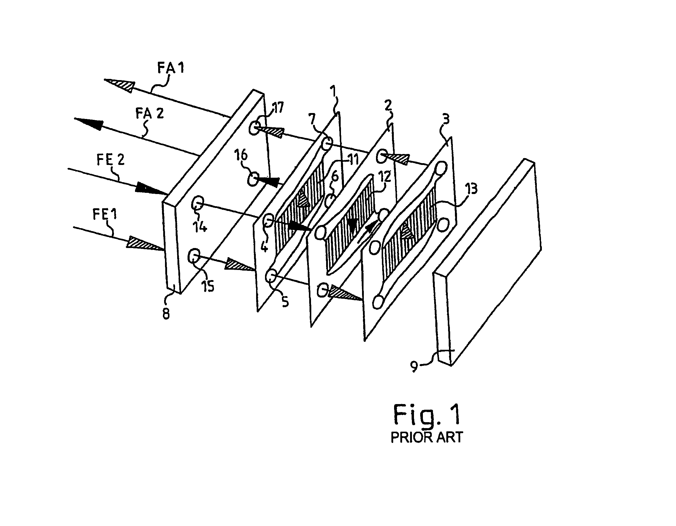
[0033]A heat exchanger according to the related art is shown in FIG. 1. The heat exchanger comprises individual plates 1, 2, 3 for transferring heat, which are soldered or welded together, packed between two cover plates 8, 9, and provided with small passages 11, 12, 13 and flow openings 4, 5, 6, 7. High-pressure CO2 flowing into an inlet opening 14 of the cover plate 8 (arrow FE2) flows through the flow opening 4 of the heat transfer plate 1 to the center heat transfer plate 2, flows downward through its passages 12 in the direction of the arrow and, from there, flows further through the flow opening 6 of the heat transfer plate 1 and out the exit opening 16 of the cover plate 8 (arrow FA2). As indicated by the shaded arrows, moreover, low-pressure CO2 (arrow FE1) flows into the inlet opening 15 of the cover plate 8, through the passages 11 of the heat transfer plate 1 from bottom to top, then further through the flow opening 5 of the heat transfer plate 2 to the heat transfer plat...


PUM


Abstract

An apparatus for transferring heat from a first fluid to a second fluid, which is separated from the first fluid, having a stack-like or saucer-like structure comprising at least two plies (1, 2, 3), in particular plates (1, 2, 3), whereby each ply (1, 2, 3) comprises a heat-transferring area that has numerous passages (11, 12, 13), an inlet area located in front of the heat-transferring area in the direction of flow, and an exit area located behind the heat-transferring area in the direction of flow is proposed in which a relatively large heat-transferring surface area is realized in a small volume, hereby ensuring uninterrupted operation, even when the pressure differential between the two fluids is great. This is achieved according to the invention in that the inlet and / or exit area comprises at least one support element (18).

Description

BACKGROUND OF THE INVENTION[0001]The invention concerns an apparatus for transferring heat from a first fluid to a second fluid—which is separated from the first fluid—having a stack-like or saucer-like structure comprising at least two plies, in particular plates.[0002]Until now, heat exchangers, for example, comprising a first passage through which a high pressure-side refrigerant flows, and a second passage—which is separated from the first passage—through which a low pressure-side refrigerant flows, are provided in a CO2 vehicle air conditioner.[0003]In order to increase the output and efficiency of the CO2 process, an “inner” or “internal” heat exchanger is provided. Refrigerant (CO2) flows through the internal heat exchanger in cocurrent or counterflow. According to this, the fluids flow through the heat exchanger once on the way from the vapor cooling apparatus to the evaporator and, the second time, they flow between the evaporator and the compressor. The main function of th...

Claims


Application Information

Patent Timeline
Patent Type & Authority Patents(United States)
IPC IPC(8): F28F3/00F28F3/08F28D9/00F28D9/02F28F9/22F28F27/02
CPCF28D9/005F28F9/0268F28F2225/08Y10S165/906F28D9/00
Inventor LEUTHNER, STEPHANBEIL, PETRA
Owner ROBERT BOSCH GMBH
Why Eureka
Try Eureka