
Cogeneration vehicle system utilizing a fuel cell car and a mobile unit as a component of the system

Inactive Publication Date: 2006-05-09
PANASONIC CORP
View PDF11 Cites 23 Cited by
  • Summary
  • Abstract
  • Description
  • Claims
  • Application Information

AI Technical Summary

Benefits of technology

[0011]Therefore, an object of the present invention is to provide a vehicle system comprising an electromobile having a fuel cell power generator mounted therein and a mobile unit to be jointed to the electromobile, the mobile unit being capable of moving and at least comprising a storage battery and a water tank, such that the system realizes cogeneration, not only while the electromobile is stopping but also while the electromobile is moving, by allowing the fuel cell mounted in the electromobile to work in cooperation with the storage battery and water tank provided in the mobile unit.

Problems solved by technology

However, in the case where fuel cells are to be used as a source of motive power for an electromobile and as a cogeneration system in a residential house or the like, a power generator incorporating a fuel cell must be installed at each of the electromobile and the residential house or the like, thereby resulting in a high installation cost.
Moreover, while it may be possible in the residential house or the like to effectively utilize substantially all of the water and heat which are produced through power generation by the fuel cell, the electromobile will only use the generated electric power and discard the generated water and heat, so that optimum use of energy is not attained in the electromobile.
Therefore, the inherent travelling capabilities of the automobile cannot be exerted during power generation.
On the other hand, cogeneration can no longer be realized once the automobile is disconnected from the housing or tent in order to allow the automobile to travel.
Thus, the conventional technique has problems which are difficult to reconcile.

Method used


Image

  • Cogeneration vehicle system utilizing a fuel cell car and a mobile unit as a component of the system
  • Cogeneration vehicle system utilizing a fuel cell car and a mobile unit as a component of the system
  • Cogeneration vehicle system utilizing a fuel cell car and a mobile unit as a component of the system

Examples


first embodiment

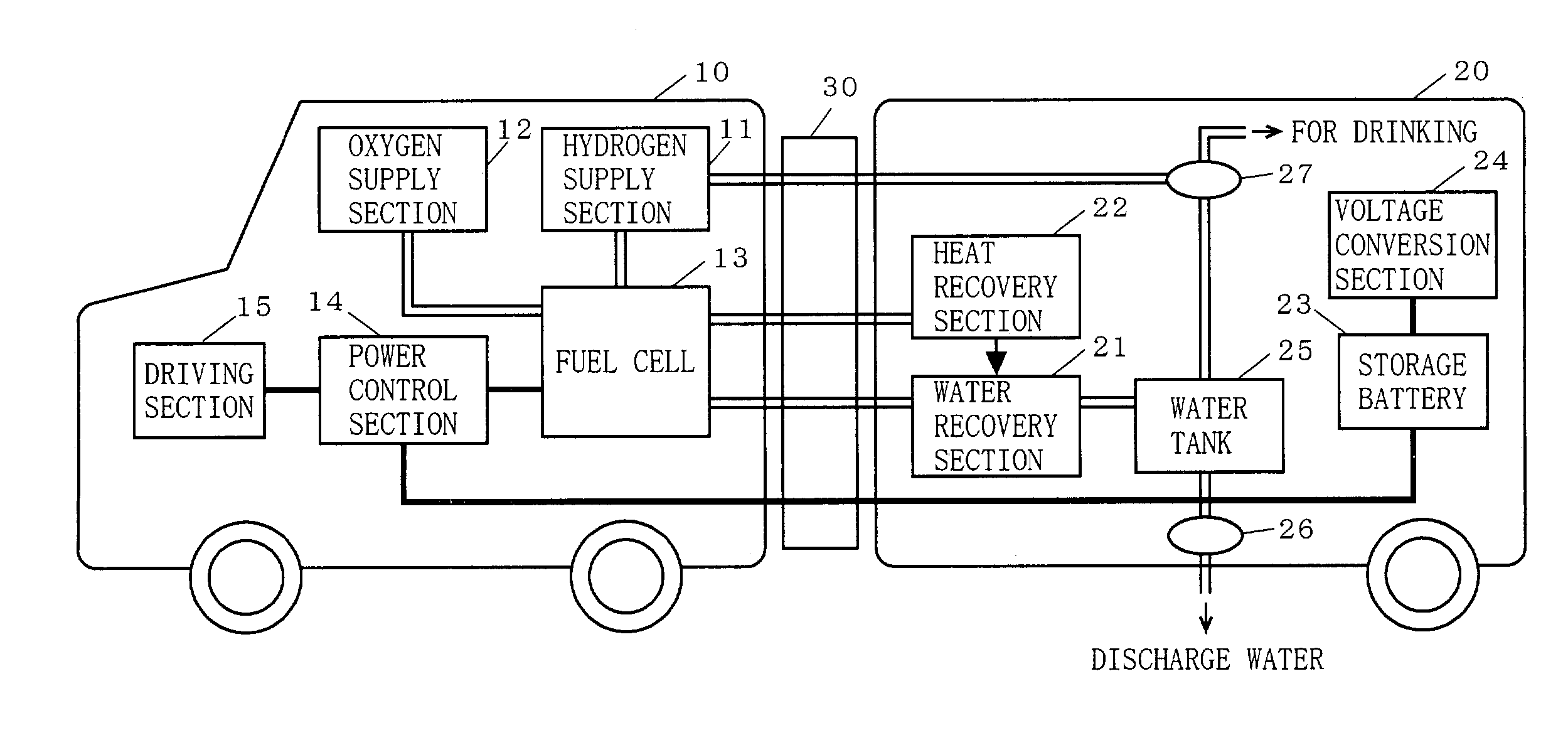
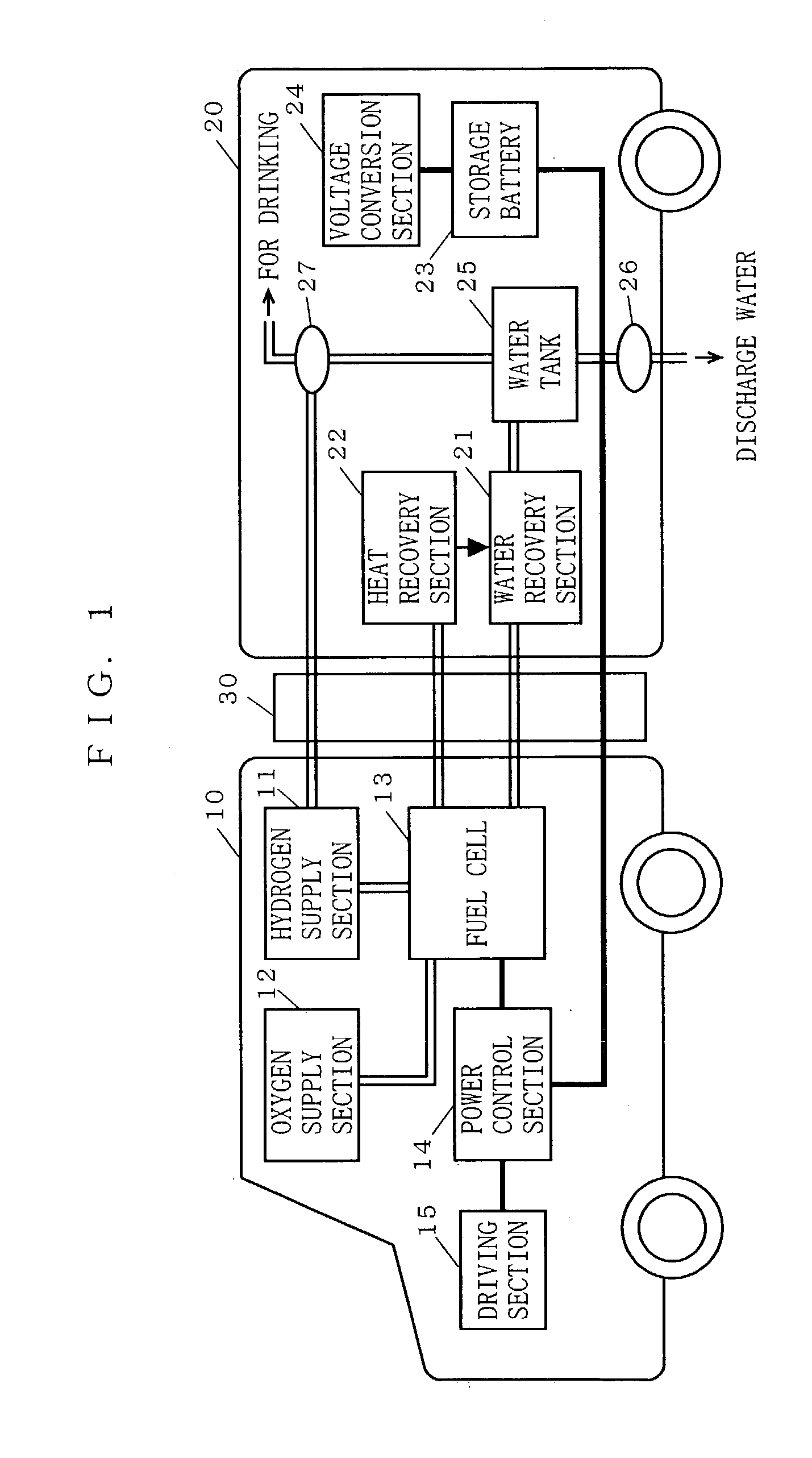
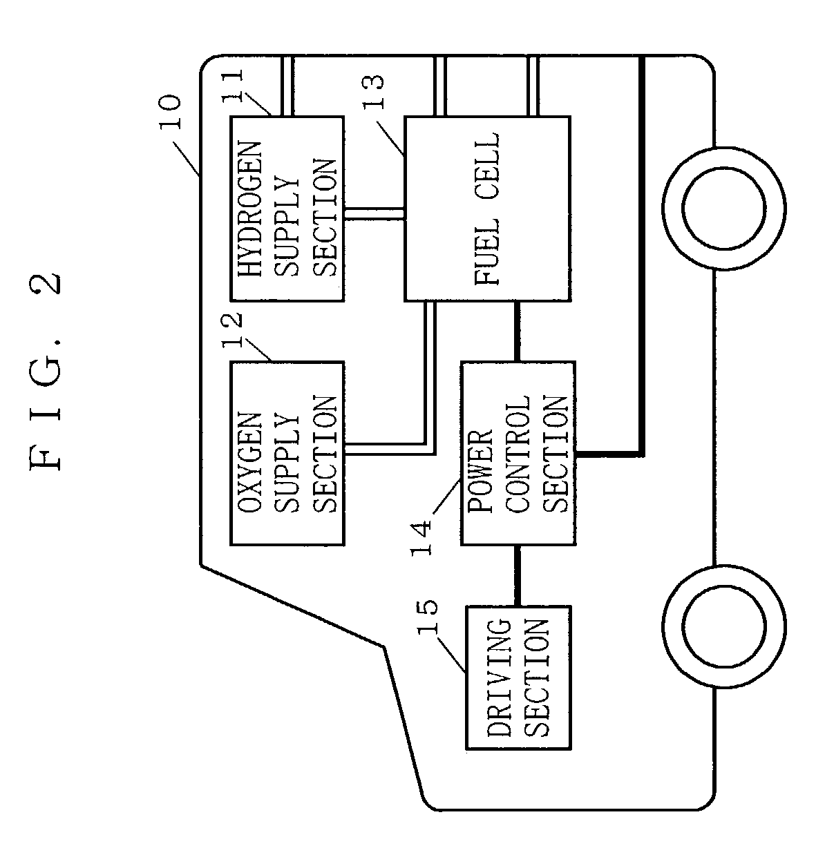
[0047]FIG. 1 is a block diagram illustrating the structure of a cogeneration vehicle system according to a first embodiment of the present invention. In FIG. 1, the system according to the first embodiment comprises a vehicle 10 incorporating a fuel cell power generator which utilizes hydrogen as a fuel and a mobile unit 20 having a living space. The vehicle 10 and the mobile unit 20 are jointed via a joint section 30. The joint section 30 joints the vehicle 10 and the mobile unit 20 in such a manner that the mobile unit 20 can be trailed by the vehicle 10 and yet energy provided from the vehicle 10 can be used for cogeneration within the mobile unit 20.

[0048]The mobile unit 20 illustrated herein is a trailer which can be conveniently moved along with the vehicle 10 and utilized by people. A typical example is a mobile house which includes daily living equipment such as a kitchen, a toilet, beds, and so on. When joined to the vehicle 10, such a mobile unit 20 will function as a so-c...

second embodiment

[0067]FIG. 3 is a block diagram illustrating the structure of a cogeneration vehicle system according to a second embodiment of the present invention. In FIG. 3, the system according to the second embodiment comprises a vehicle 10 incorporating a fuel cell power generator which utilizes hydrogen as a fuel, a mobile unit 20 having a living space, and an immobile facility 40 (such as a residential house). The vehicle 10 and the mobile unit 20 are jointed via a first joint section 30. Furthermore, the mobile unit 20 and the immobile facility 40 are jointed via a second joint section 50. The first joint section 30 joints the vehicle 10 and the mobile unit 20 in such a manner that the mobile unit 20 can be trailed by the vehicle 10 and yet energy provided from the vehicle 10 can be used for cogeneration within the mobile unit 20. The second joint section 50 joints the mobile unit 20 and the immobile facility 40 in such a manner that the energy provided from the mobile unit 20 can be used...

third embodiment

[0082]Next, specific methods for utilizing the water and heat produced in the cogeneration vehicle system (hereinafter referred to as the “produced water” and the “produced heat”, respectively) according to the first and second embodiments will be described.

[0083]As described earlier, power generation by the fuel cell 13 occurs through a reaction which is a reversal of electrolysis of water, using hydrogen and oxygen as fuels. Therefore, the fuels which have been used for the power generation all emerge as a large quantity of produced water. Moreover, a great amount of heat is also produced through the power generation by the fuel cell 13. By warming up the produced water by the produced heat, it is possible to obtain water which is hot enough for use in the kitchen or as bathing water. This hot water can also be used for room-heating purposes.

[0084]On the other hand, if the oxygen fuel supplied to the fuel cell 13 is clean, highly pure and drinkable water can be produced through th...


PUM


Abstract

There is provided a vehicle system, including an electromobile having a fuel cell power generator mounted therein, and a predetermined mobile unit jointable to the electromobile, such that cogeneration within the mobile unit can be realized even during the travel of the electromobile. Via a joint section 30, a vehicle 10 including a fuel cell 13 as a source of motive power is jointed to a mobile unit 20 capable of travelling and at least including a storage battery 23 and a water tank 25. The water produced in the fuel cell 13 is recovered by a water recovery section 21 via the joint section 30. The heat produced in the fuel cell 13 is recovered by a heat recovery section 22 via the joint section 30. The recovered water is warmed up with the recovered heat, and thereafter stored in the water tank 25. The hot water stored in the water tank 25 is utilized as hot water to be used for controlling the temperature of the mobile unit 20 or supplied as hot water. Any excess electric power generated by the fuel cell 13 is stored in the storage battery 23, and supplied onto electric wiring within the mobile unit 20.

Description

BACKGROUND OF THE INVENTION[0001]1. Field of the Invention[0002]The present invention relates to a cogeneration vehicle system utilizing a fuel cell car, and to a mobile unit which constitutes a component of the system. More particularly, the present invention relates to a cogeneration vehicle system and a mobile unit which permit water and heat, generated at the time of power generation in a fuel cell car, to be effectively utilized in a mobile unit (e.g., a trailer) which is jointed to the fuel cell car, or in an immobile facility (e.g., a residential house) by way of such a mobile unit.[0003]2. Description of the Background Art[0004]In recent years, fuel cell-based power generators have been attracting attention since such power generators have a high energy efficiency and yet are environmentally friendly. Power generation by a fuel cell occurs through a reaction which is a reversal of electrolysis of water, where hydrogen and oxygen are reacted to generate power. Therefore, the ...

Claims


Application Information

Patent Timeline
IPC IPC(8): B60K1/00B60K1/04B60L11/18H01M8/04H01M8/06H01M16/00
CPCB60K1/04B60L11/1892B60L11/1894H01M8/04007H01M8/04156H01M16/006B60L11/1887Y02B90/16H01M8/04052H01M8/04164H01M8/0662H01M2250/20H01M2250/405Y02T90/34Y02E60/50Y02T90/32B60L1/003B60L1/02B60L7/14B60L2210/30B60L2210/40B60L2240/36B60L2240/545B60L2240/662B60L2270/44B60L50/51B60L58/15B60L58/27B60L58/33B60L58/34B60L58/40Y02B90/10Y02E60/10Y02T10/70Y02T10/72Y02T90/16Y02T90/40B60L3/0046
Inventor NOMURA, NOBORUFUKUNAGA, TAKASHISUZUKI, JIRO
Owner PANASONIC CORP
Learn More