
Protective shipper

a protective and shipper technology, applied in the field of carriers, can solve the problems of increasing the risk of contamination and destruction of wafers or reducing yield, the thickness of disks also increases, and the minute particulates can destroy the integrated circuit on which they fall, so as to improve the handling and stacking of shippers

Inactive Publication Date: 2006-05-09
ENTEGRIS INC
View PDF27 Cites 40 Cited by
  • Summary
  • Abstract
  • Description
  • Claims
  • Application Information

AI Technical Summary

Benefits of technology

[0029]A feature and advantage of particular embodiments of the invention is to improve the handling and stacking of shippers by providing recessed portions therein.
[0030]A further feature and advantage of particular embodiments of the invention is that the shipper is less likely to release when shock is introduced because the latches require a horizontal component of movement within the substantially T-shaped aperture to release.
[0032]A further feature and advantage of particular embodiments of the invention is that the shipper can be produced according to film frame, wafer stack or combination configurations on the same machinery.

Problems solved by technology

The potential for contamination and destruction of a wafer or reduction in yield is ever-present throughout the various processing and packaging steps.
Particularly during the steps that take place at fabrication facilities, any minute particulates can destroy the integrated circuit on which it falls.
Moreover, disks are also are getting thinner, providing much thinner completed integrated circuit packages.
Accompanying the trend towards larger, more dense and thinner wafers, the wafers are becoming more valuable, more brittle and more easily damaged during shipment.
Although it is possible, desirable, and common to ship thicker wafers in enclosed containers that would support the wafers exclusively by their edges, using such devices to ship the thinner wafers has proven problematic due to breakage and damage of the wafers.
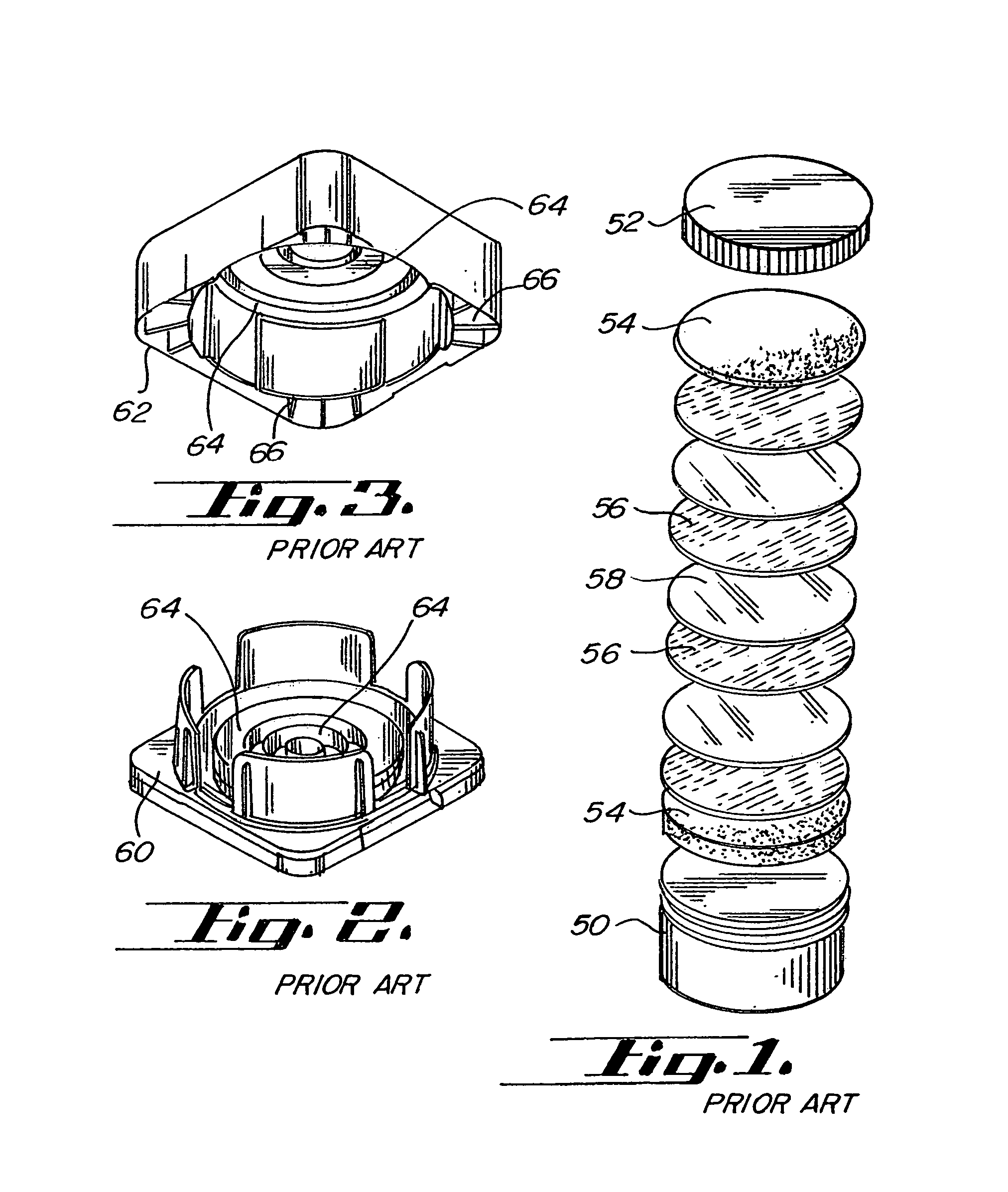
Wafer shippers that use the threaded engagements are awkward and subject to misalignment and improper attachment.
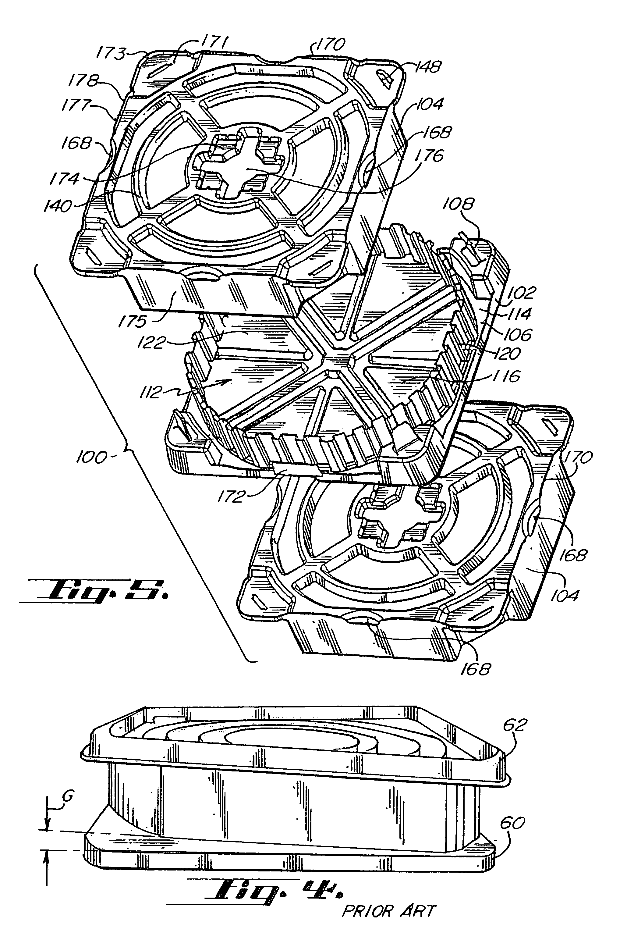
In the minimal rotation latch embodiment shown in FIG. 4, any separation stress will occur as illustrated by gap G. Such loading of the wafer shipper also can cause the deformation of the otherwise planar corners of the base to be stressed out of position, causing wobbling when placed on a planar surface and error in seating when placed on a machine interface.
Such wafer carrier has the difficultly of requiring relatively precise angular positioning for initial placement of the top cover on the base before said rotation.
In fact, such hermetic sealing is inimical to robotic handling and easy manual handling, specifically the opening and closing of the shippers.
This shock may consist of direct impact with the shipper's top cover or base, or consist of jarring of the entire shipper package.
Upon such dropping, unlatching, breakage of the shipper or damage to the wafers constitutes a failure.
The compressibility of the foam facilitates packing a variable number of wafers in a particular shipper, which can leave some undesirable discretion to the packer as to how many wafers and / or how much padding material is appropriate for a particular shipper.
Moreover, inserting excessive, or even a full load, of wafers and foam padding can, in prior art wafer shippers, particularly those with latches on the diagonal corners, cause distortion and / or bowing of the top cover and / or base.
This bowing may actually cause a gap between the top cover and base.
Such a gap is visually undesirable, may provide a pathway to contamination of the contents, and may further affect the integrity of the container during impact or shock, causing breakage or unlatching.
If the shipper is underpacked with foam or other packing material, breakage may occur at limits under normal impact limits.
Known prior art wafer carriers have provided no ready assistance in identifying an appropriate range of foam and wafer stacked thickness, which is optimal for providing security to the wafers.
Similarly, the stacked wafer shippers with the latches on the diagonally opposite corners have provided no means to minimize the visibility of the gap at the sides of the shipper when the shipper is fully loaded or slightly overloaded.
Moreover, these prior art shippers have inadequately provided structural means to the base and top cover to provide rigidity and minimize said bowing and gaps at the interface.

Method used


Image

  • Protective shipper
  • Protective shipper
  • Protective shipper

Examples


Embodiment Construction

[0065]Copending U.S. application Ser. No. 09 / 851,499, filed on May 8, 2001, hereby incorporated by reference, discloses a shock resistant variable load tolerant wafer shipper. Such wafer shipper uses axially projecting spring latches to secure said shipper in the closed position.

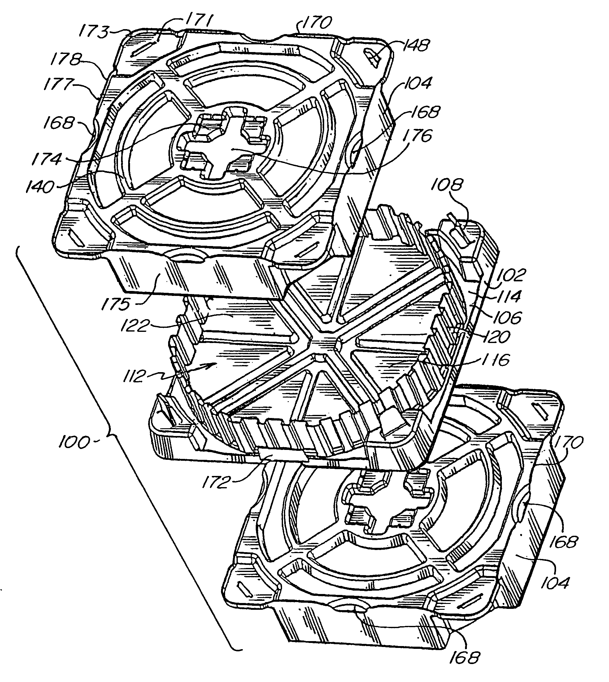
[0066]Referring to FIGS. 5–6, a shipper for protecting semiconductor wafers or film frames according to embodiments of the present invention is shown. The shipper 100 generally comprises two cooperating portions, configured as a base 102 and a top cover 104. The top cover 104 and base 102 meet at an interface 106 and are secured by latch mechanisms 108.

[0067]The base 102 has a plurality of arcuate lateral wafer support segments 110, which extend from a planar portion 114 of the base and define the wafer stack pocket 112. A floor 116 is positioned at the bottom of the pocket 112. The planar portion 114 constitutes a seat and bearing surface for the top cover edge. A side wall 120 extends around the periphery ...


PUM


Abstract

A protective shipper comprises a cover and a base that are held together by a latching member. The base is configurable to retain and protect semiconductor wafers or film frames with wafers within a storage pocket. The base comprises latching member and a support wall that defines a storage pocket. The cover encloses the storage pocket. One or both of the cover may receive recesses for gripability. The cover may receive one or more latching apertures configured to minimize unintended unlatching. The shipper of the present invention may be manufactured in a mold capable of producing film frame or wafer containing configurations of the shipper by using an interchangeable mold insert.

Description

REFERENCES TO RELATED APPLICATIONS[0001]This application is based upon U.S. Provisional Application Serial No. 60 / 305,422, which is hereby incorporated by reference herein.FIELD OF THE INVENTION[0002]This invention relates to carriers for semiconductor wafers and film frames, and more particularly relates to shippers for same.BACKGROUND OF THE INVENTION[0003]Integrated circuits are manufactured from semiconductor wafers that are conventionally round in shape and made of highly brittle silicon. Such wafers are subjected to a variety of processing steps in transforming the semiconductor wafer into integrated circuit components. The various processing steps must be performed under ultra-clean conditions to minimize the potential of contamination of the wafers as they are being processed. Each wafer may be subjected to dozens, if not hundreds of steps in its processing cycle. The potential for contamination and destruction of a wafer or reduction in yield is ever-present throughout the ...

Claims


Application Information

Patent Timeline
IPC IPC(8): B65D85/48B65D85/86H01L21/673
CPCH01L21/67353H01L21/67373H01L21/67379H01L21/67386H01L21/68
Inventor ZABKA, MICHAELNIGG, JAMES
Owner ENTEGRIS INC
Learn More