
Device and method for adjusting the pedal characteristic curve of a hybrid braking system during modified braking-force distribution

a hybrid braking system and characteristic curve technology, applied in the direction of braking systems, braking components, transportation and packaging, etc., can solve the problems of affecting the braking behavior of the vehicle and impairing driving safety

Active Publication Date: 2006-05-09
ROBERT BOSCH GMBH
View PDF9 Cites 5 Cited by
  • Summary
  • Abstract
  • Description
  • Claims
  • Application Information

AI Technical Summary

Benefits of technology

The present invention provides a device and method for keeping the braking behavior of a vehicle constant as a function of the pedal travel and force applied to the pedal. This is achieved by a control unit that can adjust the braking forces in both the hydraulic and electrical service braking systems. By controlling the braking pressure modulator and the electromechanical actuating element, the control unit ensures that the ratio between the pedal force and the total braking torque remains constant, regardless of the braking-force distribution adjustment. This eliminates the need for the driver to make adjustments and ensures a consistent and safe braking experience. Additionally, the braking system may also include regenerative braking systems that are controlled in a way that maintains a constant ratio between the pedal force and the total braking torque.

Problems solved by technology

It is known to change the braking-force distribution by increasing or reducing the braking force in the electrically operated service braking system However, this affects the braking behavior of the vehicle, since this changes the total braking force.
This significantly impairs driving safety, since the driver must constantly adjust to changes in braking behavior.

Method used


Image

  • Device and method for adjusting the pedal characteristic curve of a hybrid braking system during modified braking-force distribution
  • Device and method for adjusting the pedal characteristic curve of a hybrid braking system during modified braking-force distribution
  • Device and method for adjusting the pedal characteristic curve of a hybrid braking system during modified braking-force distribution

Examples


Embodiment Construction

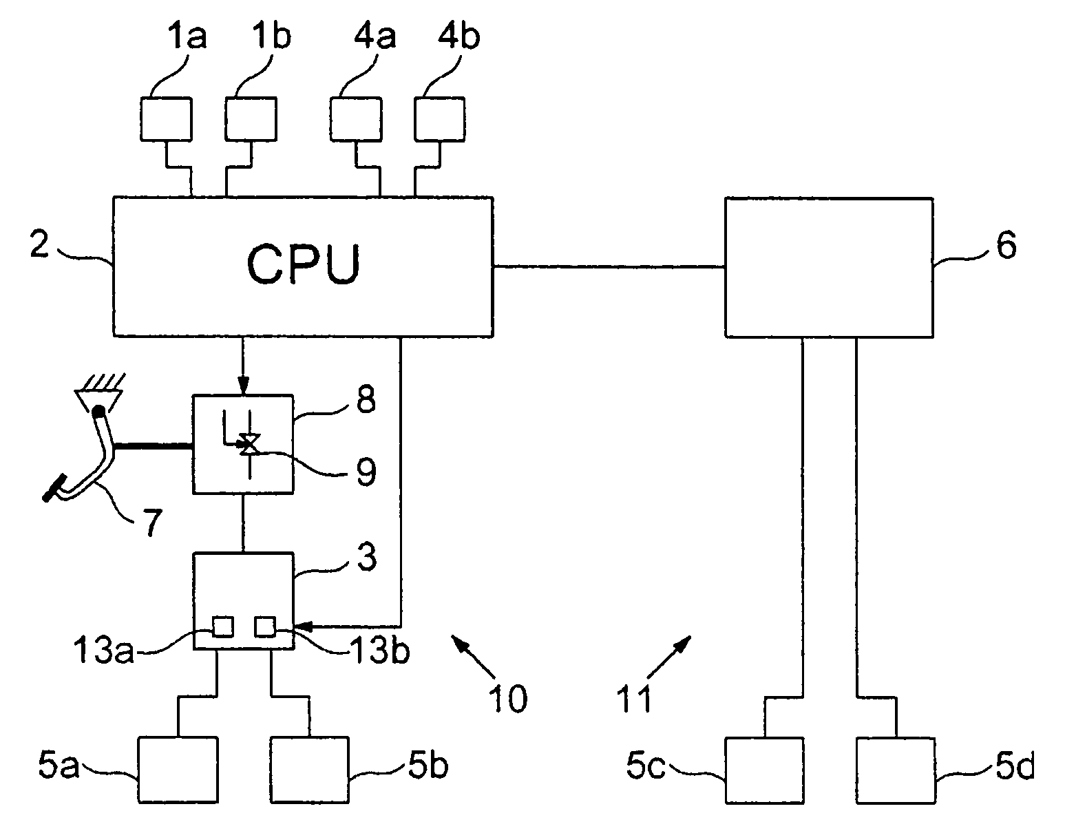
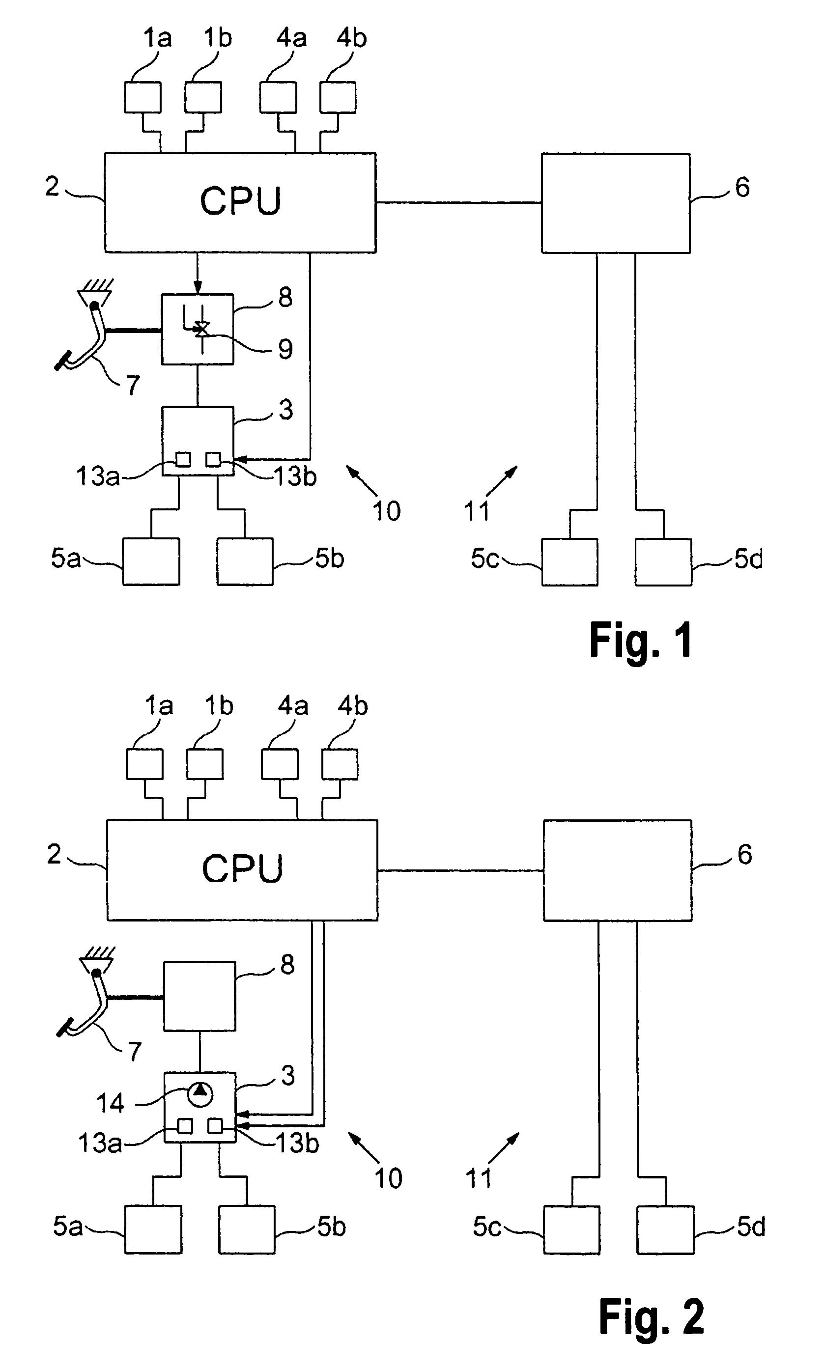
[0016]FIG. 1 shows a schematic representation of a hybrid braking system having a purely hydraulic service braking system 10 and an electrically operated service braking system 11, such as an electromechanical braking system (EMB). In this case, hydraulic service braking system 10 is assigned to the front axle including wheel brakes 5a, 5b, and electric service braking system 11 is assigned to the rear axle including wheel brakes 5c, 5d.

[0017]Braking pressure as a function of the driver's braking wish is applied to hydraulic wheel brakes 5a, 5b by a first control unit 2, and to electromechanical wheel brakes 5c, 5d by a second, separate control unit 6. However, a single, universal control unit may optionally be provided.

[0018]In the configuration shown, including two control units 2, 6, control unit 2 is preferably tasked with all functions regarding total braking system 10, 11, e.g., detecting a brake operation (of the service brake or the parking brake), and determines the brakin...


PUM


Abstract

A braking system for a vehicle is described, including a hydraulic service braking system and an electric service braking system having wheel brakes, to which braking pressure is applied when a brake pedal is operated. To maintain essentially constant vehicle braking behavior during a change in the braking-force distribution between the hydraulic and the electric service braking systems, it is proposed to provide a control unit, which is capable of varying the braking-force distribution and to equip the hydraulic service braking system with a braking pressure modulator that is controlled by the control unit and is able to effect a variable braking-force distribution as a function of the control by the control unit.

Description

FIELD OF THE INVENTION[0001]The present invention relates to a device for adjusting the pedal characteristic curve of a hybrid braking system, and to a corresponding method.BACKGROUND INFORMATION[0002]Hybrid braking systems for motor vehicles normally include a hydraulic service braking system and an electrically operated service braking system, such as an electrohydraulic brake (EHB) or an electromechanical brake (EMB). The hydraulic service braking system is usually assigned to the front axle and the electrically operated service braking system is usually assigned to the rear axle of the vehicle.[0003]When the brake pedal is operated, the braking force applied by the driver is boosted by a brake booster (vacuum brake booster) located in the hydraulic service braking system and a correspondingly increased braking pressure is applied to the brakes of the hydraulic system. The driver's braking wish is also measured by a sensor (braking value sensor) and the corresponding braking valu...

Claims


Application Information

Patent Timeline
Patent Type & Authority Patents(United States)
IPC IPC(8): B60T8/60B60T8/1766B60T8/26B60T13/12B60T13/74
CPCB60T8/1766B60T8/267B60T13/741B60T13/12B60T2270/608B60T2220/04
Inventor WEIBERLE, REINHARDSCHUMANN, FRANK
Owner ROBERT BOSCH GMBH
Learn More