Method and apparatus for grinding magnetic member and method and apparatus for treating waste fluid

a technology of magnetic members and waste fluid, which is applied in the direction of magnetic separation, chemistry apparatus and processes, manufacturing tools, etc., can solve the problems of large apparatuses, insufficient removal of small particles in sludge, and difficult to efficiently remove sludge containing these fine particles, etc., and achieve the effect of quick separation from waste fluid

Inactive Publication Date: 2006-05-09
HITACHI METALS LTD
View PDF23 Cites 29 Cited by
  • Summary
  • Abstract
  • Description
  • Claims
  • Application Information

AI Technical Summary

Benefits of technology

[0020]According to the present invention, by using the magnetic separation means having the surface magnetic flux density not smaller than 0.25 T, the sludge containing the rare-earth alloy which is difficult to draw can be separated from the waste fluid more easily.
[0021]Preferably, the sludge is further separated from the waste fluid by allowing the sludge to sediment, for example by introducing the waste fluid in a tank disposed on a downstream side of the magnetic separation means. When the magnetic separation treatment is performed to the waste fluid, the sludge which has not been drawn to the magnetic separation means is also magnetized. Therefore, by introducing the waste fluid after magnetic separation into the tank for example, the magnetized sludge in the waste fluid can be allowed to coagulate and sediment quickly in the tank. In this process, even if the sludge contains fine particles which do not sediment easily, the sludge is sedimented by the coagulation, and can be separated quickly from the waste fluid. Therefore, there is no need to use the large tank.

Problems solved by technology

However, according to the former related art, small particles in the sludge cannot be removed sufficiently.
If the small particles in the sludge are to be removed sufficiently, a large-capacity tank of about 3000 liters is required per apparatus, leading to a problem that the apparatus has to be large.
According to the latter related art, the filter is often clogged by these particles, making difficult to efficiently remove the sludge containing these fine particles.
Further, if the grinding fluid is reused without sufficient removal of the sludge, when cutting the magnetic member by a grinding blade including heat resistant resin and super hard abrasive grain, a grinding edge wears prematurely.

Method used


Image

  • Method and apparatus for grinding magnetic member and method and apparatus for treating waste fluid
  • Method and apparatus for grinding magnetic member and method and apparatus for treating waste fluid
  • Method and apparatus for grinding magnetic member and method and apparatus for treating waste fluid

Examples


Embodiment Construction

[0032]Hereinafter, an embodiment of the present invention will be described with reference to the attached drawings.

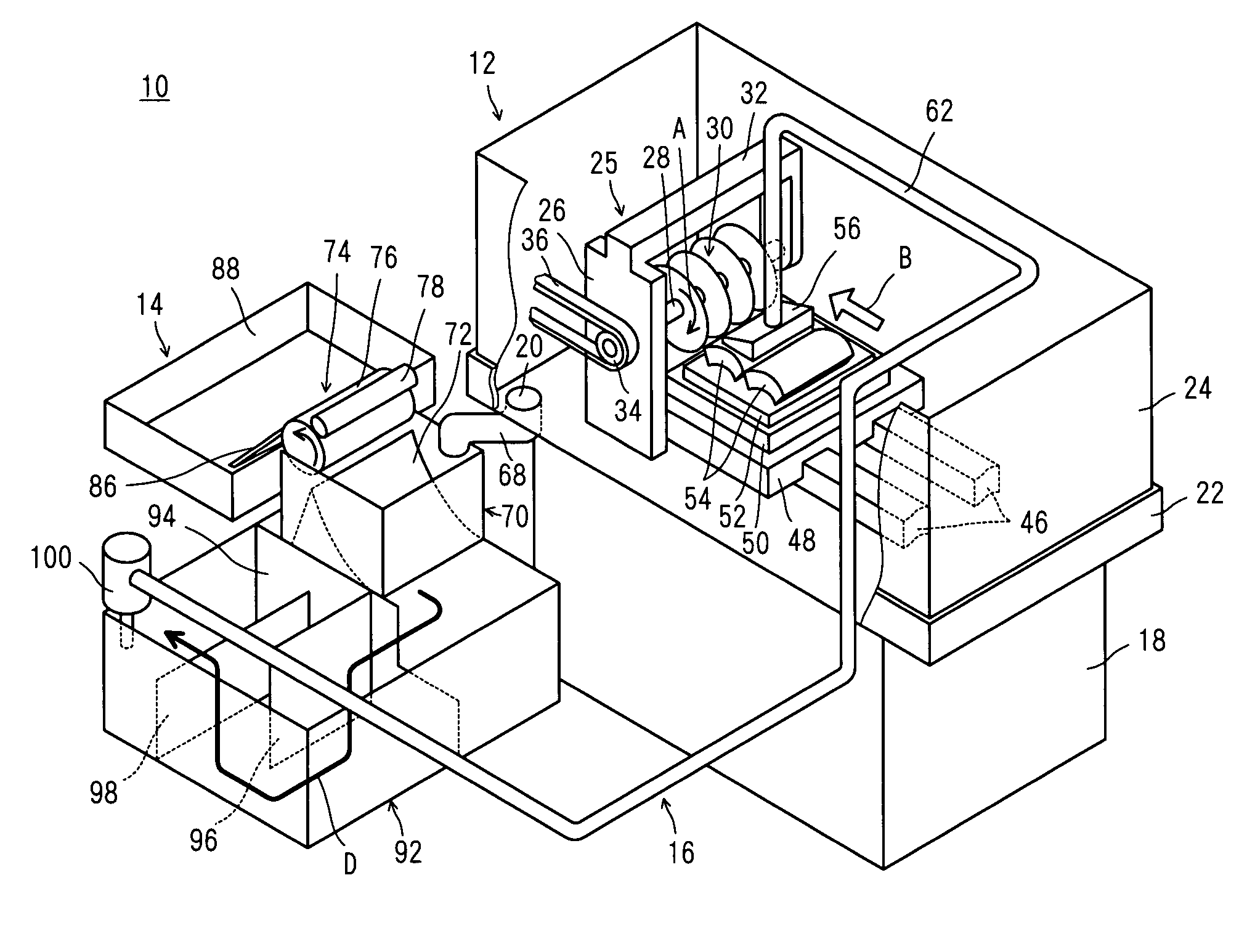
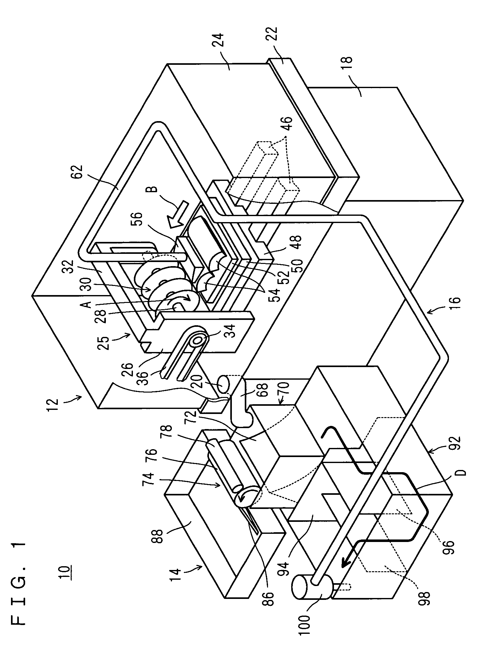
[0033]Referring to FIG. 1, an apparatus 10 for grinding a magnetic member, as an embodiment of the present invention, comprises a grinding operation portion 12 for grinding a magnetic member 54 (to be described later), a purifying portion 14 for purifying a grinding fluid 58 by separating sludge 90 (also to be described later) from the grinding fluid 58 used in the grinding operation portion 12, and a circulating portion 16 for re-supplying the purified grinding fluid 58 to the grinding operation portion 12.

[0034]The grinding operation portion 12 includes a base 18. The base 18 has an upper surface disposed with an upwardly opening pan 22 having a draining port 20 for draining the grinding fluid 58. The pan 22 is provided with upright plates 24 for preventing the grinding fluid 58 from splashing outside.

[0035]The pan 22 has an upper surface provided with an overhang X-...


PUM

PropertyMeasurementUnit
diameteraaaaaaaaaa
thicknessaaaaaaaaaa
outer diameteraaaaaaaaaa

Abstract

An apparatus for grinding a magnetic member comprises a cutting blade having a cutting edge including heat resistant resin and abrasive grain. A magnetic member including a rare-earth alloy is ground by the cutting blade while grinding fluid primarily made of water is supplied to a grinding region. A magnet separator having a surface magnetic flux density not smaller than 0.25 T magnetically separates sludge from used grinding fluid. Further, the grinding fluid is introduced into a tank, where the sludge contained in the grinding fluid is allowed to coagulate and sediment. The grinding fluid separated from the sludge is used in circulation. The same separation process can be used for separation of sludge containing a rare-earth alloy from waste fluid.

Description

BACKGROUND OF THE INVENTION[0001]1. Field of the Invention[0002]The present invention relates to a method and an apparatus for grinding a magnetic member, and a method and an apparatus for treating waste fluid. More specifically, the present invention relates to a method and an apparatus for grinding a magnetic member and a method and an apparatus for treating waste fluid in which waste grinding fluid containing sludge as waste of grinding is purified and reused.[0003]2. Description of the Related Art[0004]A related art for purifying the grinding fluid is disclosed in the Japanese Patent Laid-Open No. 10-309647. According to this related art, the grinding fluid containing impurities is stored in a tank, agitated by a nozzle for separation of sludge and abrasive grain from the grinding fluid. Then, the sludge is picked out of the tank by a magnet separator.[0005]Another related art is disclosed in the Japanese Patent Laid-Open No. 8-299717. According to this related art, a filter is ...

Claims


Application Information

Patent Timeline
Patent Type & Authority Patents(United States)
IPC IPC(8): B24B55/12B03C1/28B24B27/06B24B55/02B28D5/00B28D5/02H01F41/02
CPCB03C1/28B24B27/0683H01F41/0286B28D5/007B28D5/029B24B55/02Y02P70/10
Inventor CHIKUBA, MASANORIKONDO, SADAHIKO
Owner HITACHI METALS LTD
Why Eureka
Try Eureka