Systems and processes for providing hydrogen to fuel cells

a fuel cell and electrical generation technology, applied in the direction of other chemical processes, sustainable manufacturing/processing, separation processes, etc., can solve the problems of inability to tolerate hydrogen, large technical and economic barriers, and large stack so as to maximize the overall energetic efficiency of energy conversion and minimize the size of costly fuel cell stacks

Inactive Publication Date: 2006-05-09
AIR PROD & CHEM INC
View PDF132 Cites 89 Cited by
  • Summary
  • Abstract
  • Description
  • Claims
  • Application Information

AI Technical Summary

Benefits of technology

[0014]The disclosed fuel-cell-based electrical generation systems and processes address the deficiencies of the prior art fuel cell electrical generation systems. This is particularly true for purification of reformate hydrogen, energy-efficient PSA oxygen enrichment, heat recovery from the fuel cell stack and / or from combustion of hydrogen PSA tail gas, and thermal powering of air compression for the oxygen PSA and of any PSA vacuum pumping so as to minimize the size of the costly fuel cell stack while maximizing overall energetic efficiency of energy conversion from the raw fuel.

Problems solved by technology

External production, purification, dispensing and storage of hydrogen (either as compressed gas or cryogenic liquid) requires costly infrastructure, while storing of hydrogen fuel on vehicles presents considerable technical and economic barriers.
However, the resulting hydrogen contains contaminants, such as carbon monoxide and carbon dioxide impurities, that cannot be tolerated respectively by the PEM fuel cell catalytic electrodes in more than trace levels.
The conventional method of removing residual carbon monoxide from the hydrogen feed to PEM fuel cells has been catalytic selective oxidation, which compromises efficiency as both the carbon monoxide and a fraction of the hydrogen are consumed by low temperature oxidation, without any recovery of the heat of combustion.
Palladium diffusion membranes can be used for hydrogen purification, but have the disadvantages of delivering purified hydrogen at low pressure, and also the use of rare and costly materials.
This system is cumbersome and expensive to implement due to the large size of the adsorbers and the complexity of the valving required.
Further, the conventional PSA system use of applied energy inefficiently because of irreversible gas expansion steps as adsorbers are cyclically pressurized and depressurized within the PSA process.
Conventional PSA systems could not be applied to fuel cell power plants for vehicles, as such PSA systems are far too bulky and heavy because of their low cycle frequency and consequently large adsorbent inventory.
Another problem is the need for air compression with a substantial mechanical parasitic load to achieve high power density and high voltage efficiency with PEM fuel cells, either in the absence of PSA in prior art fuel cell systems, or to a lesser extent with the use of PSA to increase oxygen concentration.
If, as usual by the case, mechanical power is provided by an electric motor powered by the fuel cell, significant efficiency losses occur in electrical power conversion and conditioning for variable speed compressor drive, and the fuel cell stack must be substantially larger to support this parasitic load as well as the application load to which useful power is delivered.
Yet another problem arises in the need to provide heat for endothermic fuel processing reactions to generate low purity reformate hydrogen from hydrocarbon fuels (e.g. natural gas, gasoline or diesel fuel) or oxygenate fuels (e.g. methanol, ethanol or dimethyl ether).
Especially in the case of methanol reforming, which can be performed at relatively low temperature, combustion of valuable hydrogen to generate such low grade heat is extremely detrimental to overall energetic efficiency.
With a low temperature fuel cell, thermal efficiency of prior art fuel processing systems has been extremely low, as high grade fuel is consumed.
No opportunity has been found for efficient thermal integration between a high temperature fuel processor and a low temperature fuel cell in transport applications.

Method used


Image

  • Systems and processes for providing hydrogen to fuel cells
  • Systems and processes for providing hydrogen to fuel cells
  • Systems and processes for providing hydrogen to fuel cells

Examples


Embodiment Construction

FIGS. 1–5

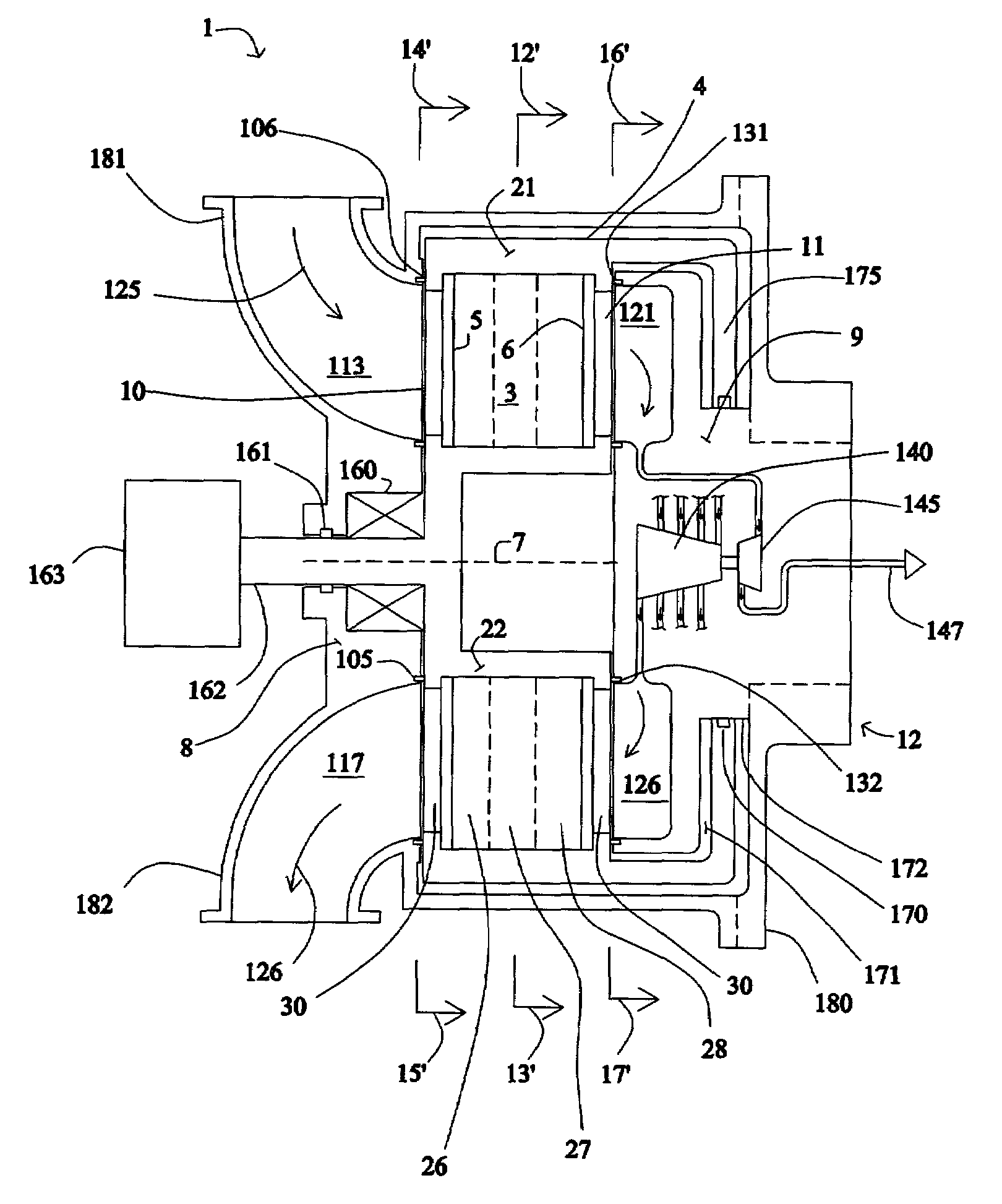
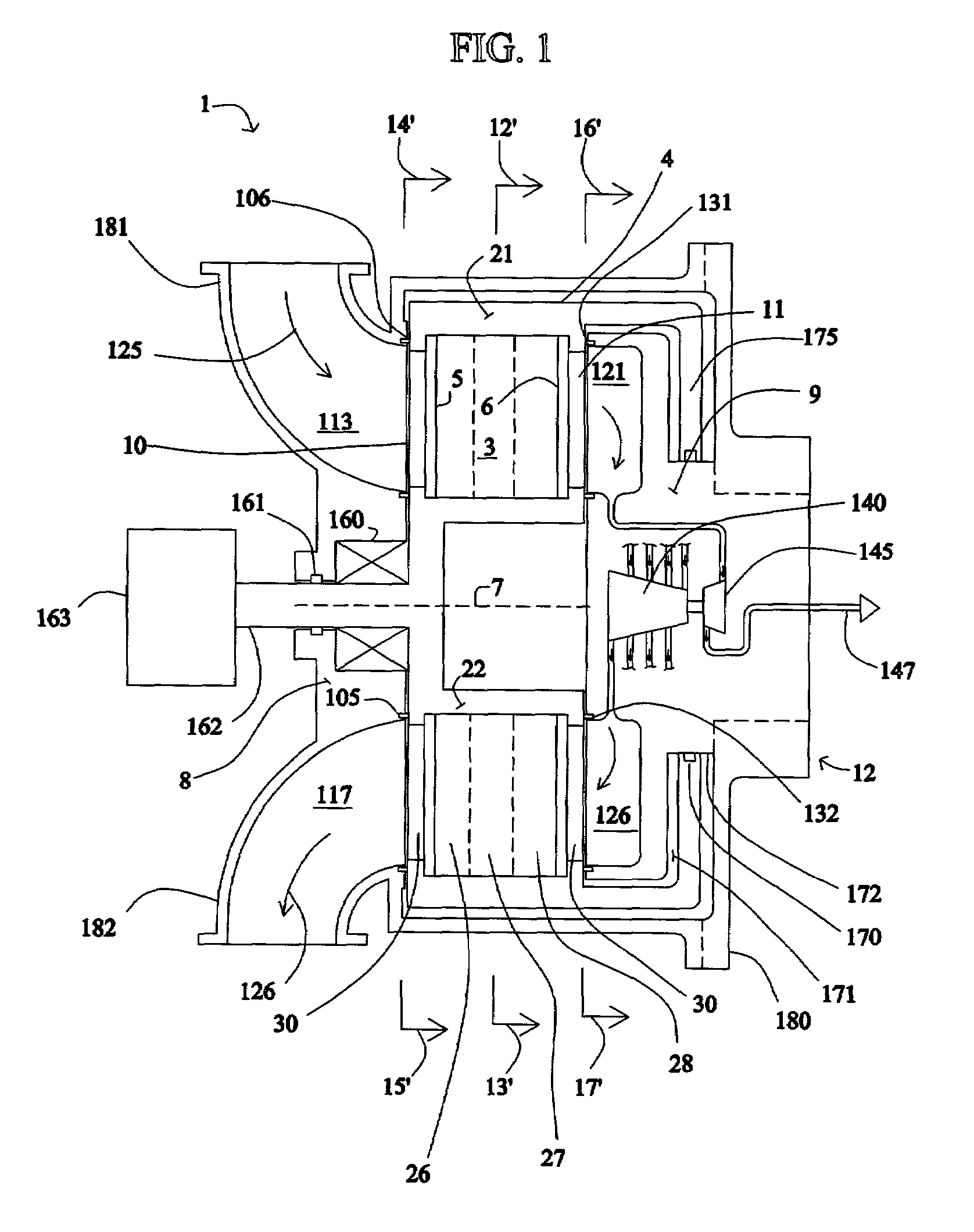
[0061]One embodiment of an oxygen-enrichment rotary PSA module for use with the described methods and systems is described below in connection with FIGS. 1–5B, but the same or similar rotary PSA module configuration could be used for hydrogen enrichment (i.e., separation) in the disclosed electrical current generating systems. As used herein, a “rotary PSA” includes, but is not limited to, either a PSA wherein the adsorbent bed rotates relative to a fixed valve face or stator or a PSA wherein the valve face or stator rotates relative to a fixed adsorbent bed.

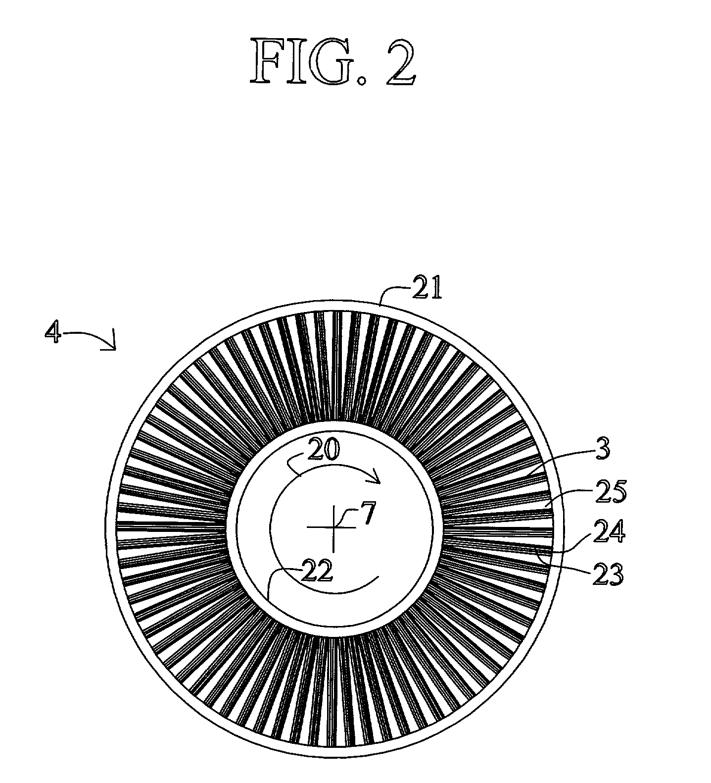
[0062]FIG. 1 shows a rotary PSA module 1, which includes a number “N” of adsorbers 3 in adsorber housing body 4. Each adsorber has a first end 5 and a second end 6, with a flow path therebetween contacting a nitrogen-selective adsorbent (for oxygen enrichment). The adsorbers are arrayed about axis 7 of the adsorber housing body. The housing body 4 is in relative rotary motion about axis 7 with first and second functiona...


PUM

PropertyMeasurementUnit
temperatureaaaaaaaaaa
operating temperaturesaaaaaaaaaa

Abstract

A process and system for providing a hydrogen-containing gas stream to a fuel cell anode that includes providing a hydrogen-containing gas stream that includes carbon monoxide, introducing the hydrogen-containing gas stream into a pressure swing adsorption module that includes at least one carbon monoxide-selective adsorbent to produce a purified hydrogen-containing gas stream, and introducing the purified hydrogen-containing gas stream to the fuel cell anode. The pressure swing adsorption module can also include a second adsorbent and / or catalyst. Also disclosed is a fuel cell system coupled to an internal combustion engine and a fuel cell system that utilizes fuel cell waste heat for vaporizing a hydrocarbon / water mixture.

Description

CROSS REFERENCE TO RELATED APPLICATIONS[0001]This application claims the benefit of Canadian Patent Application No. 2,324,699, filed Oct. 27, 2000, and Canadian Patent Application No. 2,324,702, filed Oct. 27, 2000, the disclosures of which are incorporated herein by reference.FIELD OF THE DISCLOSURE[0002]The present disclosure relates to a fuel cell-based electrical generation system that enhances the efficiency and durability of the fuel cell.BACKGROUND[0003]Fuel cells provide an environmentally friendly source of electrical current. One form of fuel cell used for generating electrical power, particularly for vehicle propulsion and for smaller scale stationary power generation, includes an anode channel for receiving a flow of hydrogen gas, a cathode channel for receiving a flow of oxygen gas, and a polymer electrolyte membrane (PEM) which separates the anode channel from the cathode channel. Oxygen gas which enters the cathode, reacts with hydrogen ions, which cross the electroly...

Claims


Application Information

Patent Timeline
Patent Type & Authority Patents(United States)
IPC IPC(8): C01B3/26B01J35/02B01J8/04H01M8/04H01M8/10C01B3/32B01D53/047B01D53/08B01J4/00B01J20/18C01B3/38C01B3/40C01B3/48C01B3/56H01M8/00H01M8/06
CPCB01D53/047C01B3/38C01B3/386C01B3/56H01M8/0612H01M8/0662B01D53/06Y02E60/50B01D53/261B01D2253/102B01D2253/108B01D2256/16B01D2257/502B01D2257/80B01D2258/0208B01D2259/40001B01D2259/40005B01D2259/402B01D2259/4541C01B2203/00C01B2203/0233C01B2203/025C01B2203/0283C01B2203/043C01B2203/047C01B2203/0475C01B2203/0495C01B2203/066C01B2203/0811C01B2203/0822C01B2203/0827C01B2203/0883C01B2203/1076C01B2203/1211C01B2203/1223C01B2203/1229C01B2203/1241C01B2203/1288C01B2203/146C01B2203/147C01B2203/82H01M8/04022H01M8/04029H01M8/04156Y02C10/08Y02E60/523Y02C20/40Y02P20/10Y02P20/129Y02P20/52
Inventor KEEFER, BOWIE G.SAWADA, JAMES A.JOHANNES, ERIK P.ROY, SURAJITBROWN, MICHAEL J.
Owner AIR PROD & CHEM INC
Why Eureka
Try Eureka