Intermittent coating apparatus and intermittent coating method
- Summary
- Abstract
- Description
- Claims
- Application Information
AI Technical Summary
Benefits of technology
Problems solved by technology
Method used
Image

Examples
first embodiment
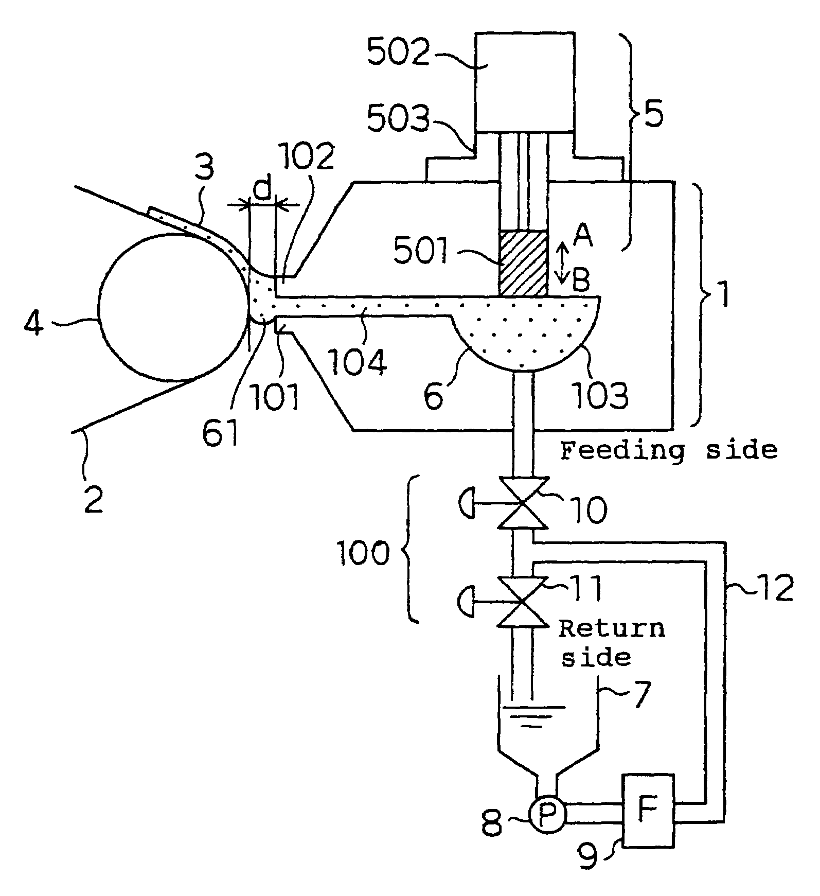
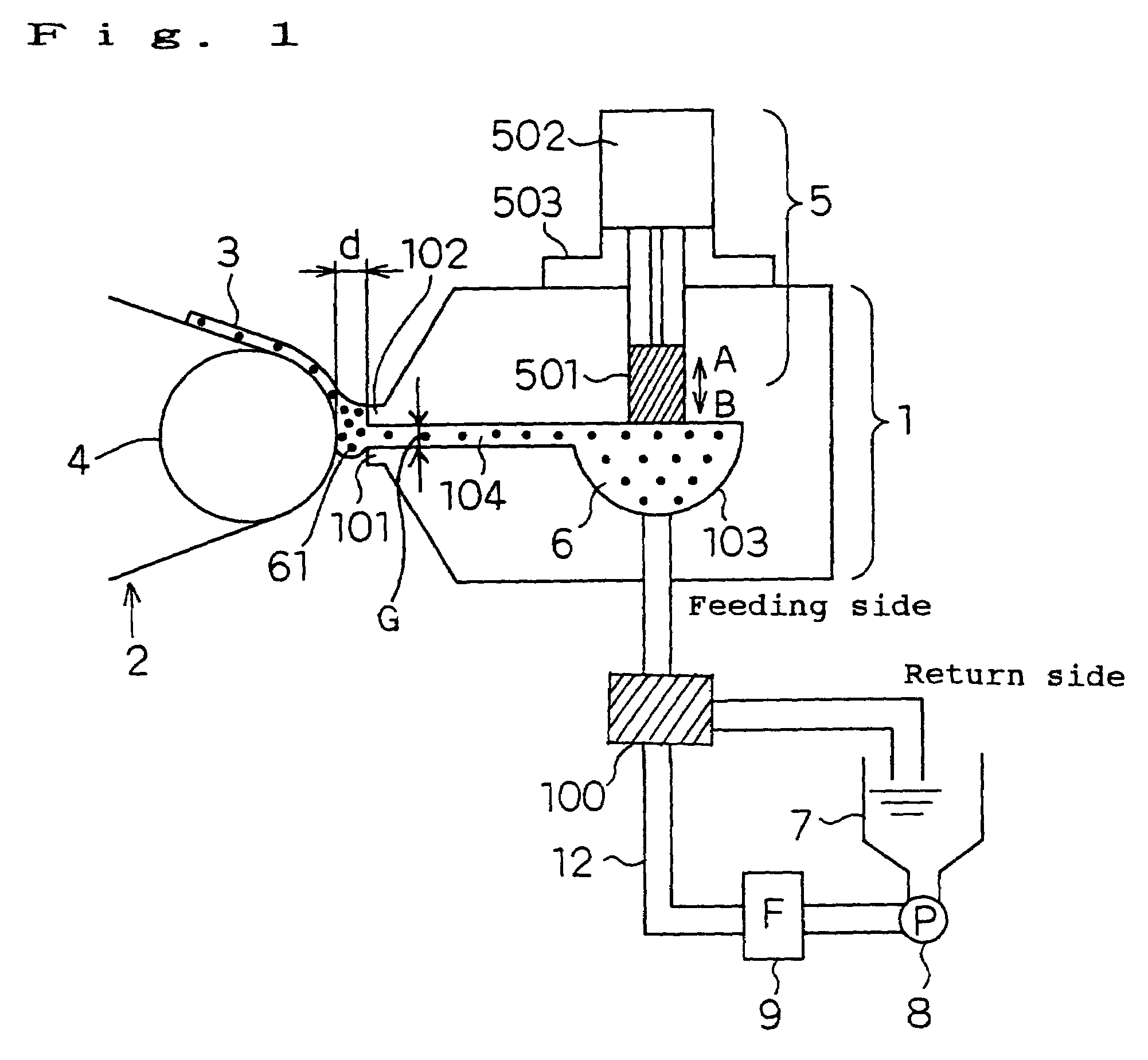
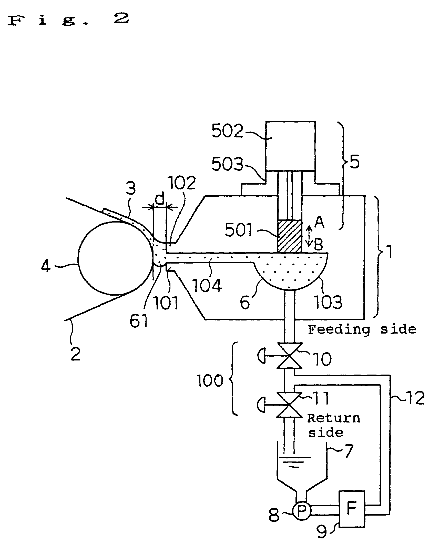
[0073]FIG. 1 shows a schematic diagram illustrating an example of a coating apparatus and a coating method of a first embodiment according to the present invention.
[0074]A nozzle 1 is configured by an upstream lip 101, a downstream lip 102, a manifold 103 which is a reservoir of a paint 6 and a slit 104 for extrusion. A width of the slit 104 is represented by G.
[0075]A driving unit 5 is configured by an air cylinder 502 which moves a piston 501 in a direction indicated by an arrow A or B and a jig 503 which is used to mount the air cylinder 502 on the nozzle 1. The paint 6 contained in a tank 7 is fed by a pump 8 from the tank 7 by way of a filter 9 and intermittent means 100 into the manifold 103 of the nozzle 1 so that it is extruded from the slit 104.
[0076]A base material 2 is supported by a back roll 4 and disposed so as to be apart from a tip of the downstream lip 102 by a distance d of 50 to 500 mm which is adequately set dependently on a viscosity of the paint. The paint 6 ex...
second embodiment
[0118]FIG. 3 shows a schematic diagram of a coating apparatus and a coating method of a second embodiment of the present invention.
[0119]The second embodiment is characterized in that an operation time A msec of a piston 501 to suck a paint 6 into a sucking device (not shown) in a nozzle 1 and an operation time B msec of the piston 501 to return the paint 6 from the sucking device into the nozzle 1 are set in a relation of A5.
[0120]Furthermore, the second embodiment is characterized also in that the piston 501 is driven with a piezoelectric element 502. Furthermore, the second embodiment uses a three-way valve as intermittent means 100.
[0121]Members other than the driving unit 5 of the second embodiment may be those of the first embodiment, which are not described in particular.
[0122]When the paint 6 is not to be coated, feeding of the paint 6 to the nozzle 1 is stopped by switching a flow of the paint 6 fed from the pump 8 by the intermittent means 100 to a return side, and simulta...
third embodiment
[0128]FIG. 4 is a schematic diagram of an apparatus to carry out a coating apparatus of a third embodiment according to the present invention.
[0129]The third embodiment is characterized in that it comprises a bellowphragm 501 which is moved by moving a pin of a driving unit 5 to suck and discharge a paint 6 into and out of a nozzle 1 and a paint reservoir 61. Other members of the third embodiment may be those of the first embodiment, which are not described in particular.
[0130]In the third embodiment, a circumferential end of the bellowphragm 501 is fixed to an inside of a nozzle 1 and a central portion of the bellowphragm 501 is moved with the pin in a direction indicated by an arrow A or B.
[0131]Accordingly, a sucking speed and a returning speed of the bellowphragm 501 can be kept always constant under no influence due to friction with a wall surface in the nozzle 1, whereby the third embodiment is capable of remarkably enhancing an intermittent pitch of coated film layers which a...
PUM
| Property | Measurement | Unit |
|---|---|---|
| Time | aaaaa | aaaaa |
| Time | aaaaa | aaaaa |
| Length | aaaaa | aaaaa |
Abstract
Description
Claims
Application Information
 - Generate Ideas
- Intellectual Property
- Life Sciences
- Materials
- Tech Scout
- Unparalleled Data Quality
- Higher Quality Content
- 60% Fewer Hallucinations
Browse by: Latest US Patents, China's latest patents, Technical Efficacy Thesaurus, Application Domain, Technology Topic, Popular Technical Reports.
© 2025 PatSnap. All rights reserved.Legal|Privacy policy|Modern Slavery Act Transparency Statement|Sitemap|About US| Contact US: help@patsnap.com