Tone-control circuit and method for conditioning respective frequency bands of an audio signal

a tone control circuit and frequency band technology, applied in the field of electronic circuits, can solve the problems of low-noise potentiometers that are relatively expensive, complex, and lack the consistent performance required by turntablists, and achieve the effect of reducing the area of the circuit board and lowering the cost of the devi

Inactive Publication Date: 2006-05-09
RANE CORPORATION
View PDF13 Cites 8 Cited by
  • Summary
  • Abstract
  • Description
  • Claims
  • Application Information

AI Technical Summary

Benefits of technology

[0023]Such a circuit provides useful levels of isolation between the frequency bands of an audio signal with significantly fewer components than prior circuits. Thus, such a circuit costs significantly less to manufacture than prior circuits, and also occupies a reduced circuit board area, which contributes to a significantly lower cost of a device such as an audio mixer that incorporates the filter circuit.

Problems solved by technology

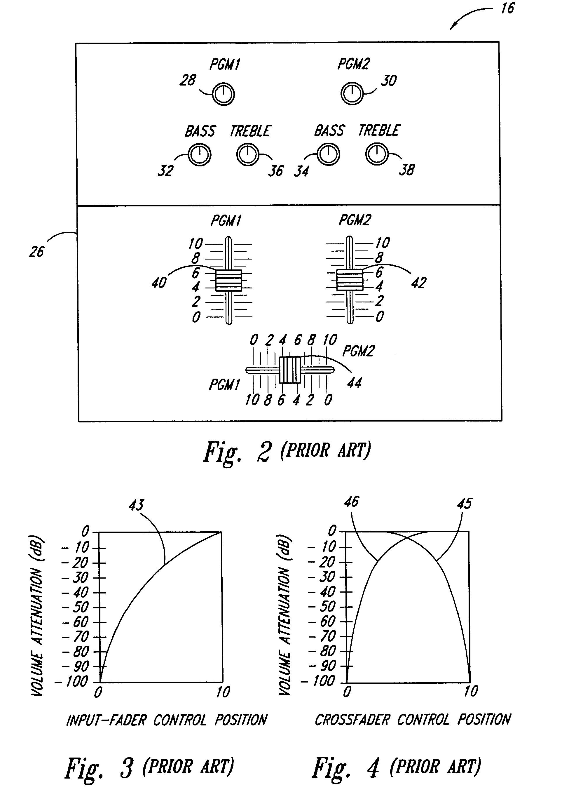
Unfortunately, movement of the fader controls 40 and 42 often adds audible levels of noise called “travel” noise, to PGM1 and PGM2, respectively.
But these low-noise potentiometers are relatively expensive, and, like their cheaper counterparts, soon wear down to a point where they generate unacceptable travel noise or allow unacceptable signal bleed through, and thus must be replaced.
Unfortunately, such designs are frequently expensive, complex, and lack the consistent performance required by turntablists.
For example, the filter may cause the controls 40 and 42 to exhibit inappropriate volume-increase and volume-decrease rates—often called “attack” and “decay” rates, respectively—which may compromise the ability of the filter to remove travel noise without adversely altering the performance of the turntablist.
In addition, such designs frequently require a separate gain-controlled amplifier for each fader control 40 and 42, thus making the input-fader circuit too complex and expensive for compact performance mixers.
Unfortunately, these techniques often exhibit the same shortcomings as the above-described techniques.
Furthermore, many crossfader contour controls lack a constant-power setting.
Thus, differences in the input-fader position-attenuation characteristics between the practice and performance mixers can ruin the turntablists performance!
Moreover, because the design of the crossfader circuit is often complex, the crossfader circuit often requires a relatively large number of components and thus contributes significantly to the cost, size, and power consumption of the mixer 16.
This makes it virtually impossible for the turntablist to add effects to more than one of the PGM1, PGM2, and MASTER signals while he plays his piece.
But unfortunately, because the effects box 18 is a relatively expensive item, most turntablists can afford to have only one.
Unfortunately, the frequency cutoff slopes of many tone-control circuits are not steep enough to allow for such independent gain control.
But the filters used in a 4th-order tone-control circuit often have relatively large numbers of components, and thus often increase the cost, size, and power consumption of the mixer 16.

Method used


Image

  • Tone-control circuit and method for conditioning respective frequency bands of an audio signal
  • Tone-control circuit and method for conditioning respective frequency bands of an audio signal
  • Tone-control circuit and method for conditioning respective frequency bands of an audio signal

Examples


Embodiment Construction

[0055]FIGS. 5A–C are respective views of an audio mixer according to an embodiment of the invention, and FIG. 5D is a block diagram of a sound system that incorporates the audio mixer of FIGS. 5A–C.

[0056]FIG. 5A is a top view of a mixer 50 according to an embodiment of the invention. For example, the mixer 50 may be a TTM 54 Performance Mixer manufactured by RANE Corporation of Mukilteo, Wash. The mixer 50 includes a control panel 52, which includes an all-band gain control 54 and bass-band and treble-band gain controls 56 and 58 for the PGM1 signal, and which includes an all-band gain control 60 and bass-band and treble-band gain controls 62 and 64 for the PGM2 signal. The all-band gain controls 54 and 60 function like the controls 28 and 30, respectively, of FIG. 2. The bass-band and treble-band gain controls 56, 58, 62, and 64 function like the controls 32, 36, 34, and 38, respectively, of FIG. 2, but the tone-control circuits of the mixer 50 (not shown in FIG. 5A) are significan...


PUM


Abstract

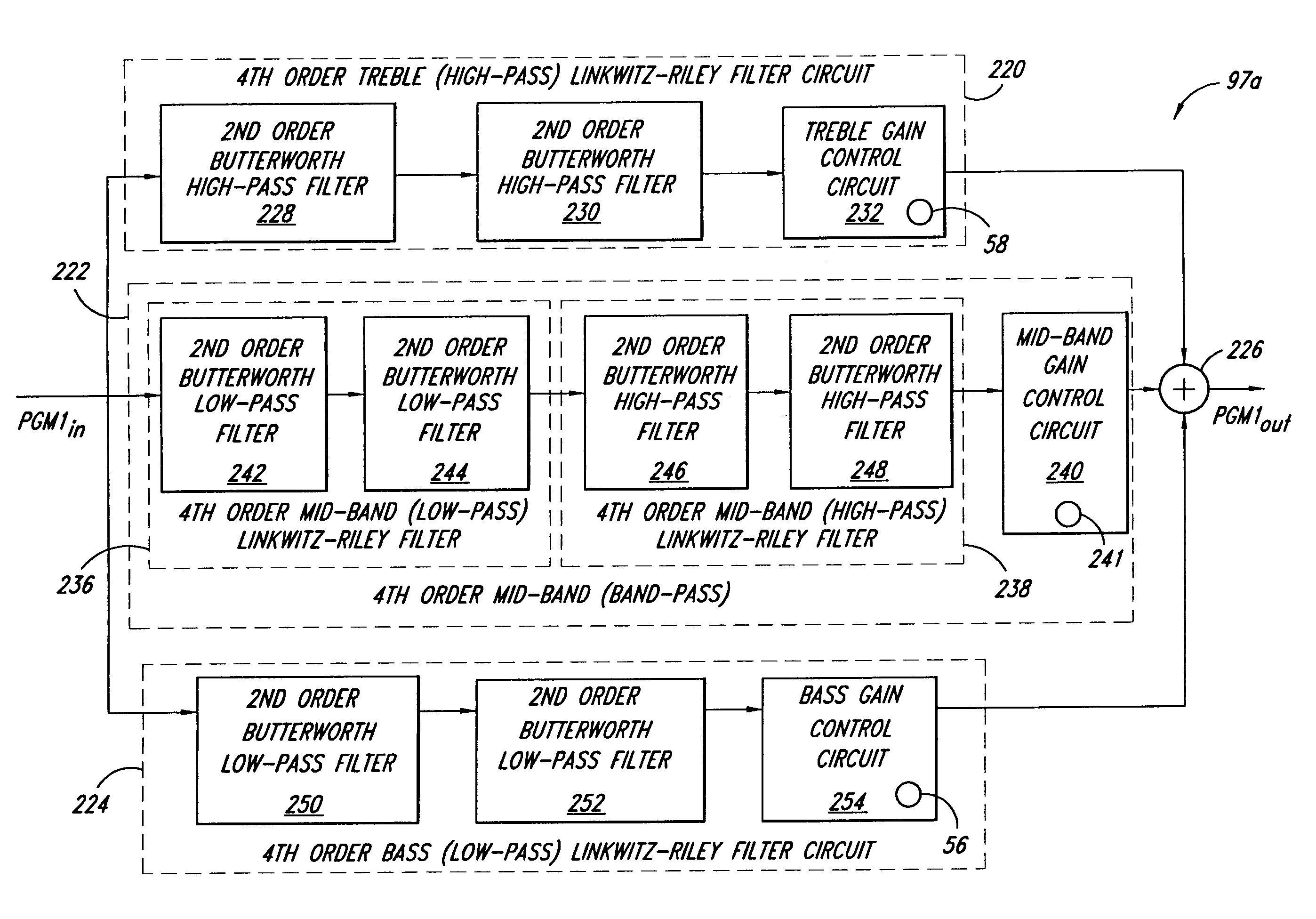
An audio tone-control circuit includes 4th-order low-pass, 4th-order band-pass, and 4th-order high-pass filter circuits. The 4th-order low-pass filter circuit has a first phase response and receives and filters an audio signal and generates a first output signal therefrom. The 4th-order band-pass filter circuit has a second phase response that is substantially equal to the first phase response and receives and filters the audio signal to generate a second output signal. The 4th-order high-pass filter circuit has a third phase response substantially equal to the first and second phase responses and receives and filters the audio signal to generate a third output signal. The audio-signal circuit also includes a combining circuit that combines the first, second and third output signals into a combined signal. Furthermore, the filter circuits may be 2nd-order filter circuits instead of 4th-order filter circuits.

Description

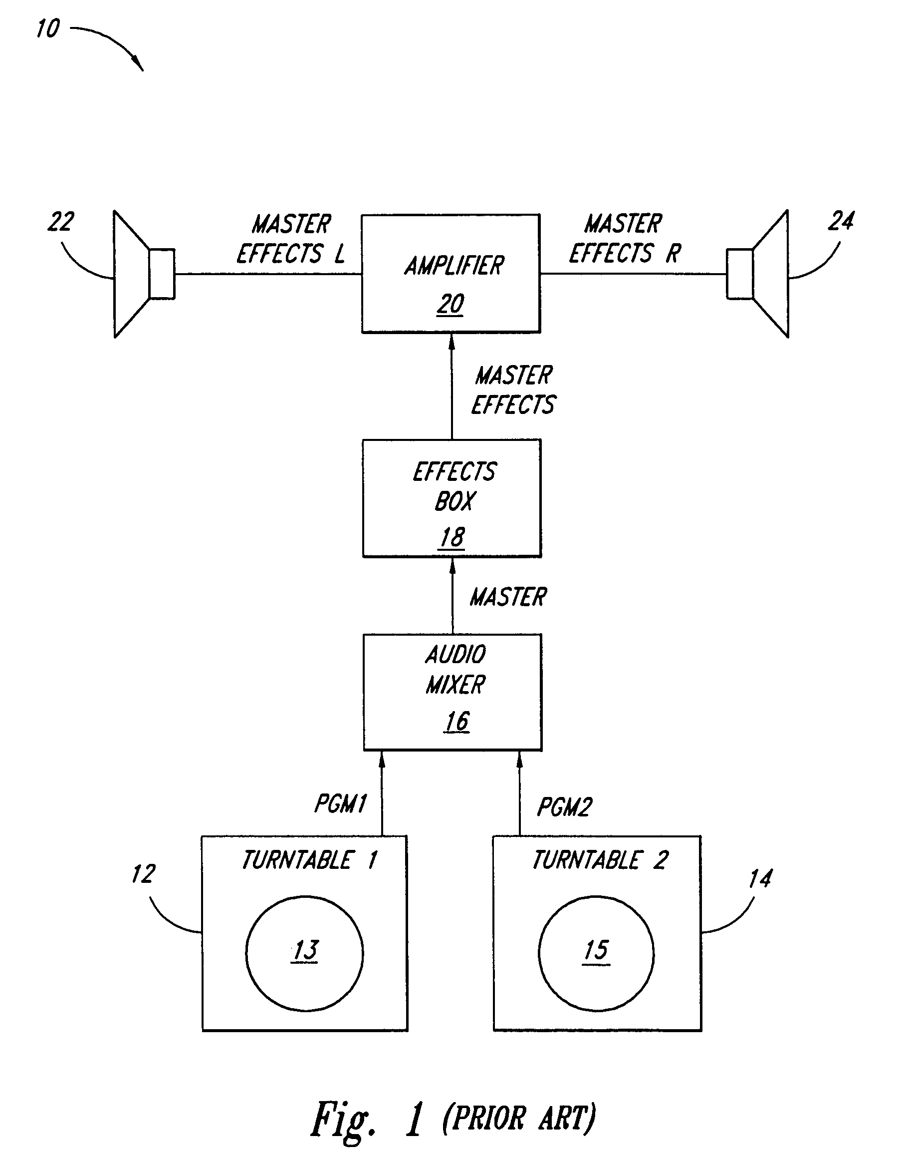
TECHNICAL FIELD[0001]The invention relates generally to electronic circuits, and more particularly, to an improved tone-control circuit and method for controlling the gains of one or more of the bass, mid, and treble frequency bands of an audio signal.BACKGROUND OF THE INVENTION[0002]Within the last few years, the music world has witnessed the birth and increasing popularity of a new type of composer / performer known as a “turntablist”. Generally, a turntablist performs a musical piece by manually rotating one or more conventional phonographic records to generate musical sounds.[0003]FIG. 1 is a schematic block diagram of a conventional sound system 10 that is used by many of today's turntablists. The system 10 includes a pair of turntables 12 and 14, which amplify the sounds from respective phonographic records 13 and 15. The turntables 12 and 14 respectively provide first (PGM1) and second (PGM2) program audio signals to an audio mixer 16, which mixes these signals together to gene...

Claims


Application Information

Patent Timeline
Patent Type & Authority Patents(United States)
IPC IPC(8): H03G5/00
CPCH04H60/04H03H11/1286H04R5/04H04R5/02
Inventor JEFFS, PHILIP R.BOHN, DENNIS A.
Owner RANE CORPORATION
Why Eureka
Try Eureka