Combined exhaust duct and mixer for a gas turbine engine

Active Publication Date: 2006-05-16
PRATT & WHITNEY CANADA CORP
View PDF16 Cites 123 Cited by
  • Summary
  • Abstract
  • Description
  • Claims
  • Application Information

AI Technical Summary

Benefits of technology

[0006]One object of the present invention is to provide a lower cost and smaller structure

Problems solved by technology

The lobes of a multi-lobe type noise suppressing nozzle are generally unsu

Method used


Image

  • Combined exhaust duct and mixer for a gas turbine engine
  • Combined exhaust duct and mixer for a gas turbine engine
  • Combined exhaust duct and mixer for a gas turbine engine

Examples


Embodiment Construction

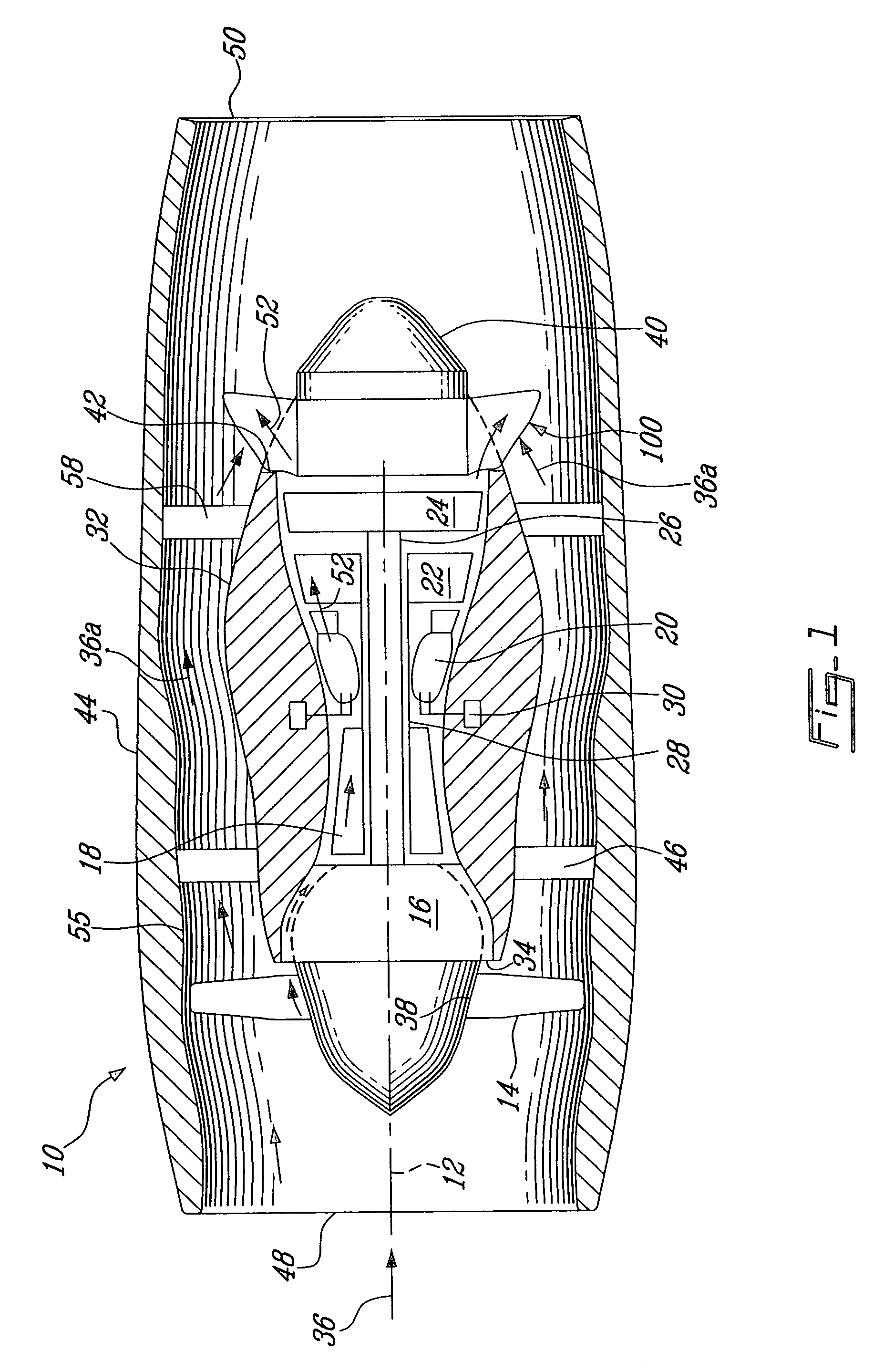
[0018]Referring to the drawings, particularly FIG. 1, an exemplary gas turbine engine 10 includes in serial flow communication about a longitudinal central axis 12, fan or rotor blades 14, a conventional low pressure compressor 16, a conventional high pressure compressor 18, a conventional annular combustor 20, a conventional high pressure turbine 22, and a conventional low pressure turbine 24. The low pressure turbine 24 is securely connected to both the low pressure compressor 16 and the fan blades 14 by a first rotor shaft 26, and the high pressure turbine 22 is securely connected to the high pressure compressor 18 by a second rotor shaft 28. Conventional fuel injecting means 30 are provided for powering the engine 10.

[0019]A conventional annular casing 32 surrounds the engine 10 from the low pressure compressor 16 to the low pressure turbine 24 and defines, with the low pressure compressor 16, a low pressure compressor inlet 34 for receiving a portion of ambient air 36 therethro...


PUM

PropertyMeasurementUnit
Radiusaaaaaaaaaa
Waveaaaaaaaaaa
Distanceaaaaaaaaaa

Abstract

A gas turbine engine including a gas exhaust duct assembly which comprises an annular shroud forming at least a section of an inner wall of a gas exhaust duct, a plurality of strut members radially projecting from the shroud, and a plurality of insert members. The strut members are disposed in a circumferentially, substantially equally spaced-apart relationship, and extend in a substantially axial direction. The insert members each define a circumferential section of an outer wall of the gas exhaust duct and are positioned in a space between adjacent strut members, and are secured to same. The gas exhaust duct is thereby defined between inner surfaces of the insert members and the outer surface of the shroud, and is circumferentially divided by the respective strut members, for directing exhaust gases rearwardly in an axial direction, meanwhile surrounding flow passages are defined by outer surfaces of the insert members and the strut members in combination, for directing surrounding air flows rearwardly in an axial, radial and inward direction.

Description

FIELD OF THE INVENTION[0001]This invention relates to bypass gas turbine engines and more particularly to combining an exhaust duct and mixer for such engines.BACKGROUND OF THE INVENTION[0002]In the course of gas turbine engine development various dynamic concepts have evolved which require the mixing of two separate gas flows, such as bypass duct flow and exhaust gases, in an efficient manner. This mixing is required because the two gas flows are at widely varying temperatures and / or pressures and they must be combined together to form a single homogeneous flow of gases in order to reduce exhaust gas noise. A number of different noise suppression and gas mixing nozzles have been developed for use with aircraft gas turbine engines, some of which are independently attached to the engine around the engine exhaust duct, and some of which are combined with the engine exhaust duct. Nevertheless, the engine exhaust duct functions not only to discharge exhaust gases but also as a stationar...

Claims


Application Information

Patent Timeline
IPC IPC(8): F02K1/38F02K3/04F02K1/46F02K3/02
CPCF02K1/386F02K3/02F02K1/46Y10T29/49346
Inventor RAGO, GIUSEPPE
Owner PRATT & WHITNEY CANADA CORP
Why Eureka
Try Eureka