Method of forming a fuel feed passage in the feed arm of a fuel injector

a fuel injector and feed arm technology, applied in the field of fuel injectors, can solve the problems of hardware distress and ultimately failure, fuel coking and carbon formation within the fuel feed passage, and increase the pressure drop through the fuel passage undesirably, so as to reduce the increase the fuel flow velocity and the convection heat transfer coefficient, and reduce the effect of initial cross-sectional flow area

Active Publication Date: 2006-05-16
DELAVAN
View PDF13 Cites 18 Cited by
  • Summary
  • Abstract
  • Description
  • Claims
  • Application Information

AI Technical Summary

Problems solved by technology

This serves to lower the operating temperatures of the fuel nozzle, which in turn, reduces the potential for fuel coking and carbon formation within the fuel feed passage.
This can lead to undesirable thermal gradients within the combustion system causing hardware distress and ultimately failure.
However, as the diameter of the fuel passage decreases to reduce wetted wall temperatures, the pressure drop through the fuel passage increases undesirably.
When combined with the manufacturing challenges and inefficiencies associated with machining small diameter passageways, it is clear that there are significant disadvantages in such a design.
The contoured swirl vanes, like the small diameter passages described above, present manufacturing challenges.

Method used


Image

  • Method of forming a fuel feed passage in the feed arm of a fuel injector
  • Method of forming a fuel feed passage in the feed arm of a fuel injector
  • Method of forming a fuel feed passage in the feed arm of a fuel injector

Examples


Embodiment Construction

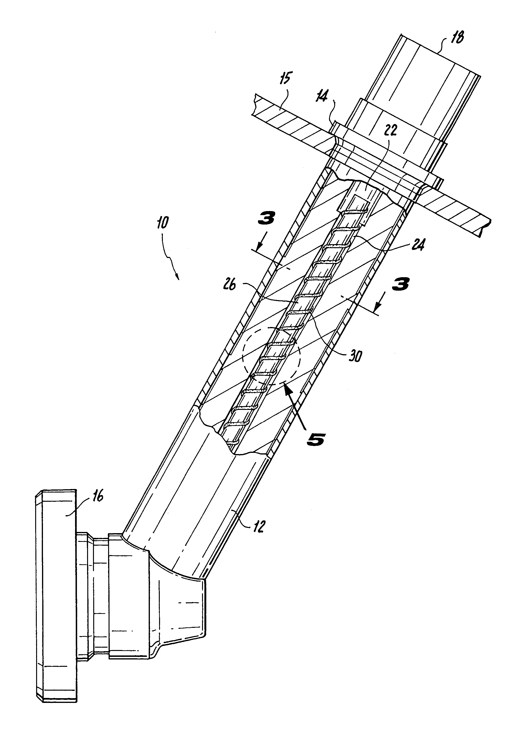
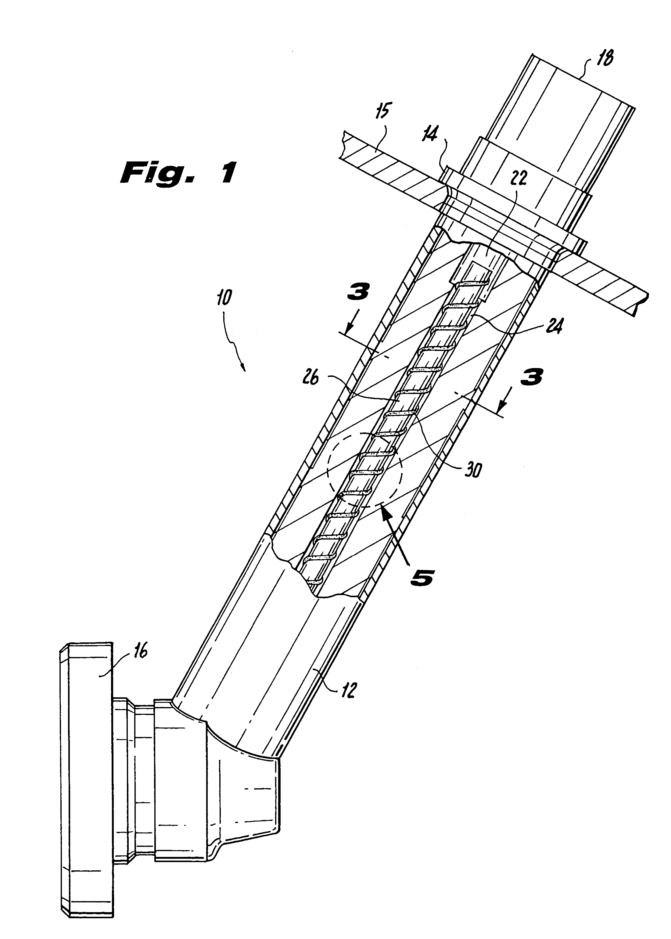
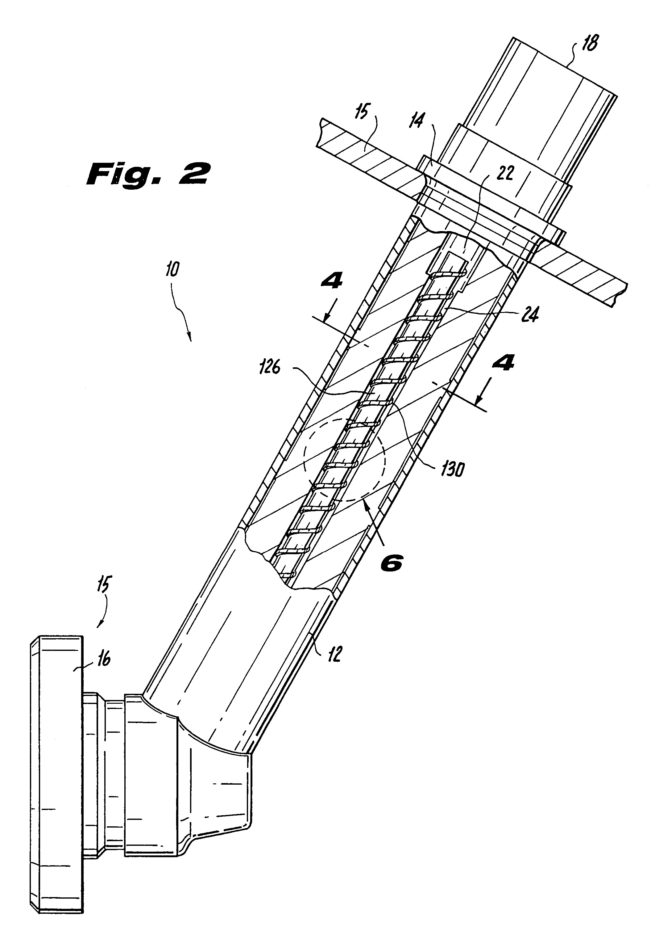
[0022]The subject invention is directed to a new, useful and cost-effective method of forming a fuel feed passage in the feed arm of a fuel injector, primarily used in a gas turbine engine. As described in detail below, the fuel feed passage formed by the method of the subject invention has a relatively large diameter, as compared to a traditional fuel feed passage which has a relatively small diameter designed to produce higher fuel flow velocities and heat transfer coefficients for a given fuel flow rate and fuel temperature. This reduces the wetted wall temperatures within the fuel feed passage. Typically, a larger diameter fuel feed passage, such as that which is initially formed in the injector of the subject invention, will lead to lower fuel flow velocities and lower heat transfer coefficients, resulting in higher wetted wall temperatures. However, this is alleviated in a fuel flow passage formed in accordance with the methodology of the subject invention, by positioning a sh...


PUM

PropertyMeasurementUnit
temperatureaaaaaaaaaa
convection heat transfer coefficientaaaaaaaaaa
temperaturesaaaaaaaaaa

Abstract

A method is disclosed for forming a fuel feed passage in the feed arm of a fuel injector. The method includes the steps of providing a fuel feed passage in the feed arm of a fuel injector, whereby the fuel feed passage has an initial cross-sectional flow area that corresponds with an initial fuel flow velocity, an initial convection heat transfer coefficient and initial localized wetted wall temperatures for the fuel feed passage, for a given fuel flow rate and fuel temperature. The method further includes decreasing the initial cross-sectional flow area of the fuel feed passage so as to increase the fuel flow velocity and the convection heat transfer coefficient for the fuel feed passage, while lowering the localized wetted wall temperatures for the fuel feed passage, without varying the given fuel flow rate and fuel temperature.

Description

BACKGROUND OF THE INVENTION[0001]1. Field of the Invention[0002]The subject invention is directed to fuel injectors, and more particularly, to a cost-effective method of forming a large diameter fuel feed passage in the feed arm of a fuel injector employed in a gas turbine engine.[0003]2. Background of the Related Art[0004]In designing fuel nozzles for gas turbine engines, it is desirable to increase fuel passage convection or heat transfer coefficients so as to reduce the wetted wall temperatures within the fuel feed passage. This serves to lower the operating temperatures of the fuel nozzle, which in turn, reduces the potential for fuel coking and carbon formation within the fuel feed passage. Fuel coking within the nozzle can cause reductions in fuel flow. This can lead to undesirable thermal gradients within the combustion system causing hardware distress and ultimately failure.[0005]Typically, to control the wetted wall temperature in the fuel passage of a fuel injector, the di...

Claims


Application Information

Patent Timeline
Patent Type & Authority Patents(United States)
IPC IPC(8): F02C3/00F02C7/22F02C7/00F02M53/08F02M55/02F23D11/38F23R3/28
CPCF02C7/222F02M53/08F02M55/02F23D11/383F23R3/28Y10T29/49348F23K2301/204Y02T50/672F05D2250/25F23D2900/00016F23K2300/204Y02T50/60F02C7/224F02M53/04F23D11/36F23D14/78
Inventor THOMPSON, KEVIN E.HELTON, GREGORY L.
Owner DELAVAN
Why Eureka
Try Eureka