Ultrasonic flow sensor using quasi-helical beam

a quasi-helical beam and ultrasonic technology, applied in the direction of instruments, heat measurement, specific gravity measurement, etc., to achieve the effect of improving the accuracy of the voluntaria

Inactive Publication Date: 2006-05-16
ONICON INC
View PDF8 Cites 16 Cited by
  • Summary
  • Abstract
  • Description
  • Claims
  • Application Information

AI Technical Summary

Benefits of technology

[0011]The acoustic energy paths, when projected onto a cross-section perpendicular to the axis of the pipe, approximate chordal paths. In a preferred embodiment of the present invention, where the insertion depth of the transducers is 25% of the pipe's diameter and the transducers are beamed horizontally, these paths define a quasi-helix that appears, in cross-section, like an equilateral triangle. That is, the path can conceptually be constructed by drawing an equilateral triangle, cutting through one vertex and then moving the cut ends of the triangle apart along a line perpendicular to the plane of the triangle by a selected amount corresponding to a flow measurement distance between the two transducers. The associated transit time is responsive to the flow rates along those paths and the fluid flow intersecting those paths provides an approximation of the volumetric flow in the entire pipe. Hence, the volumetric accuracy is improved. Further improvement is possible when more than one probe is used and is particularly effective when the respective associated acoustic energy paths have different locations in the pipe cross-section. Such improvement is particularly evident when the flow profile is not uniform.

Problems solved by technology

Such improvement is particularly evident when the flow profile is not uniform.

Method used


Image

  • Ultrasonic flow sensor using quasi-helical beam
  • Ultrasonic flow sensor using quasi-helical beam
  • Ultrasonic flow sensor using quasi-helical beam

Examples


Embodiment Construction

[0022]In studying the detailed description, the reader may be aided by noting definitions of certain words and phrases throughout this patent document. Whenever those definitions are provided, those of ordinary skill in the art should understand that in many, if not most instances, such definitions apply to both preceding and following uses of such defined words and phrases. At the outset of this Description, one may note that the terms “include” and “comprise,” as well as derivatives thereof, mean inclusion without limitation; and the term “or,” is inclusive, meaning and / or.

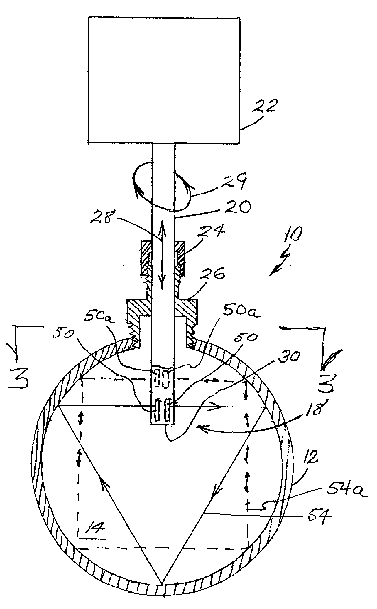
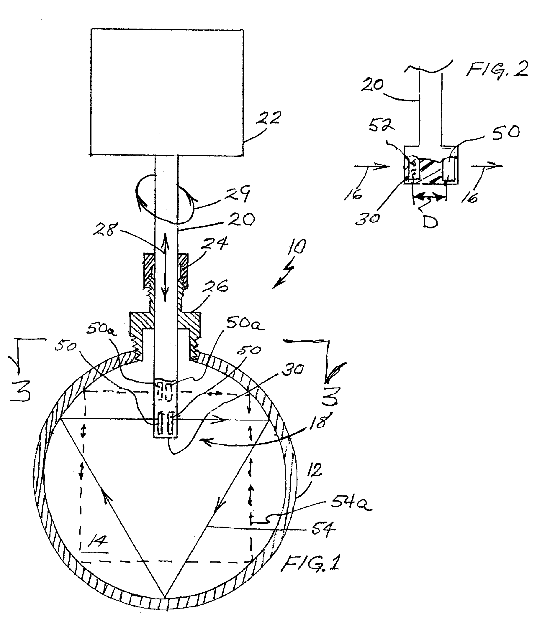
[0023]The term “insertion probe” as used herein, denotes an item elongated along a probe axis and designed to be inserted into a pipe or other vessel so that a sensing element on, or closely adjacent, the inserted end of the probe is at a selected probe axial insertion depth and orientation with respect to that pipe or vessel. Although much of the ensuing discussion is directed toward in-field insertion of probe...


PUM


Abstract

A probe type acoustic transit-time flow sensor has paired transducers arranged to generate quasi-helical acoustic beams making a plurality of reflective contacts with a pipe's interior wall. The transducers in each pair are spaced apart along the flow axis so that transit-time measurements can be used both to measure the internal diameter of the pipe and to determine a flow rate. These measurements are combined to yield a volumetric flow rate. Various numbers of pairs of transducers can be put on a single probe or on multiple probes and used to provide a more accurate representation of a flow profile and therefore a more accurate volumetric flow determination.

Description

CROSS-REFERENCE TO RELATED APPLICATIONS[0001]This application is a continuation-in-part of the inventor's U.S. Ser. No. 10 / 946,834, filed Sep. 22, 2004 and now issued as U.S. Pat. No. 6,973,842.BACKGROUND OF THE INVENTION[0002]The present invention relates to acoustic apparatus and methods for fluid flow measurement. More specifically, it relates to apparatus and methods for compensating for variations in the internal diameters of pipes in which flow is measured, for measuring flow in the presence of flow profile variations, for optimizing the location and orientation of a flow sensor and for detecting accumulation of pipe wall deposits.[0003]Insertion probes for detecting the flow of fluids are typically mounted in round pipes having internal diameters that are not precisely known. Because these probes are generally used to measure flow rate by sampling a small portion of the flow profile and deriving from that measurement the volumetric flow rate based upon an assumed internal pip...

Claims


Application Information

Patent Timeline
Patent Type & Authority Patents(United States)
IPC IPC(8): G01F1/66G01F15/00G01F15/18
CPCG01F1/66G01F1/662G01F1/667G01F15/00G01F15/18G01F5/00G01N2291/02836
Inventor FELLER, MURRAY F
Owner ONICON INC
Why Eureka
Try Eureka