
Radio frequency triggered directed energy munition

a directed energy and radio frequency technology, applied in the direction of directed energy weapons, weapons, training adaptation, etc., can solve the problems of low-flying, fast moving and/or maneuvering weapons (e.g., missiles and/or artillery shells), affecting the flight time of ballistic anti-missile systems, and experiencing non-negligible delays

Active Publication Date: 2006-05-16
COMP SCI A OF NV
View PDF10 Cites 10 Cited by
  • Summary
  • Abstract
  • Description
  • Claims
  • Application Information

AI Technical Summary

Benefits of technology

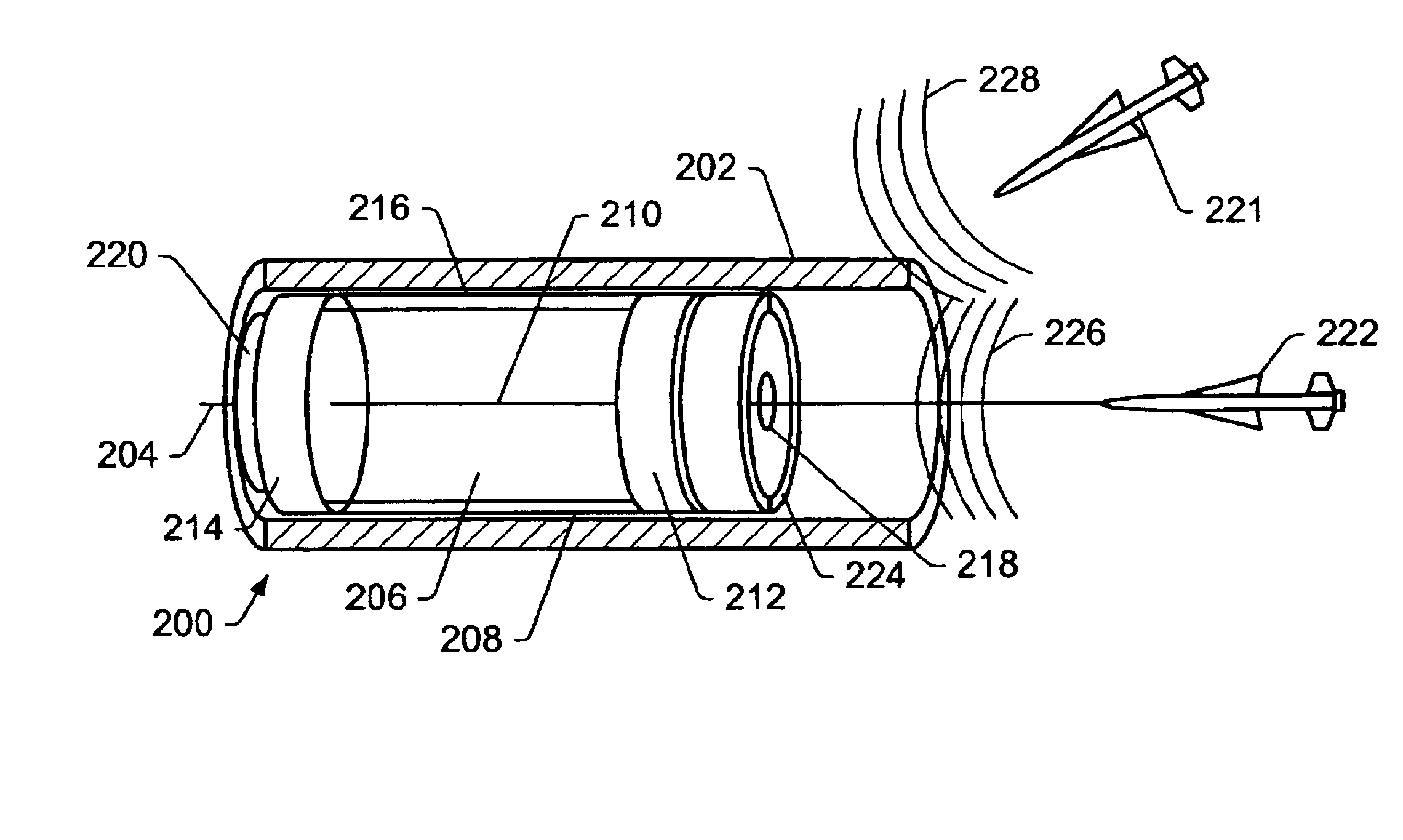
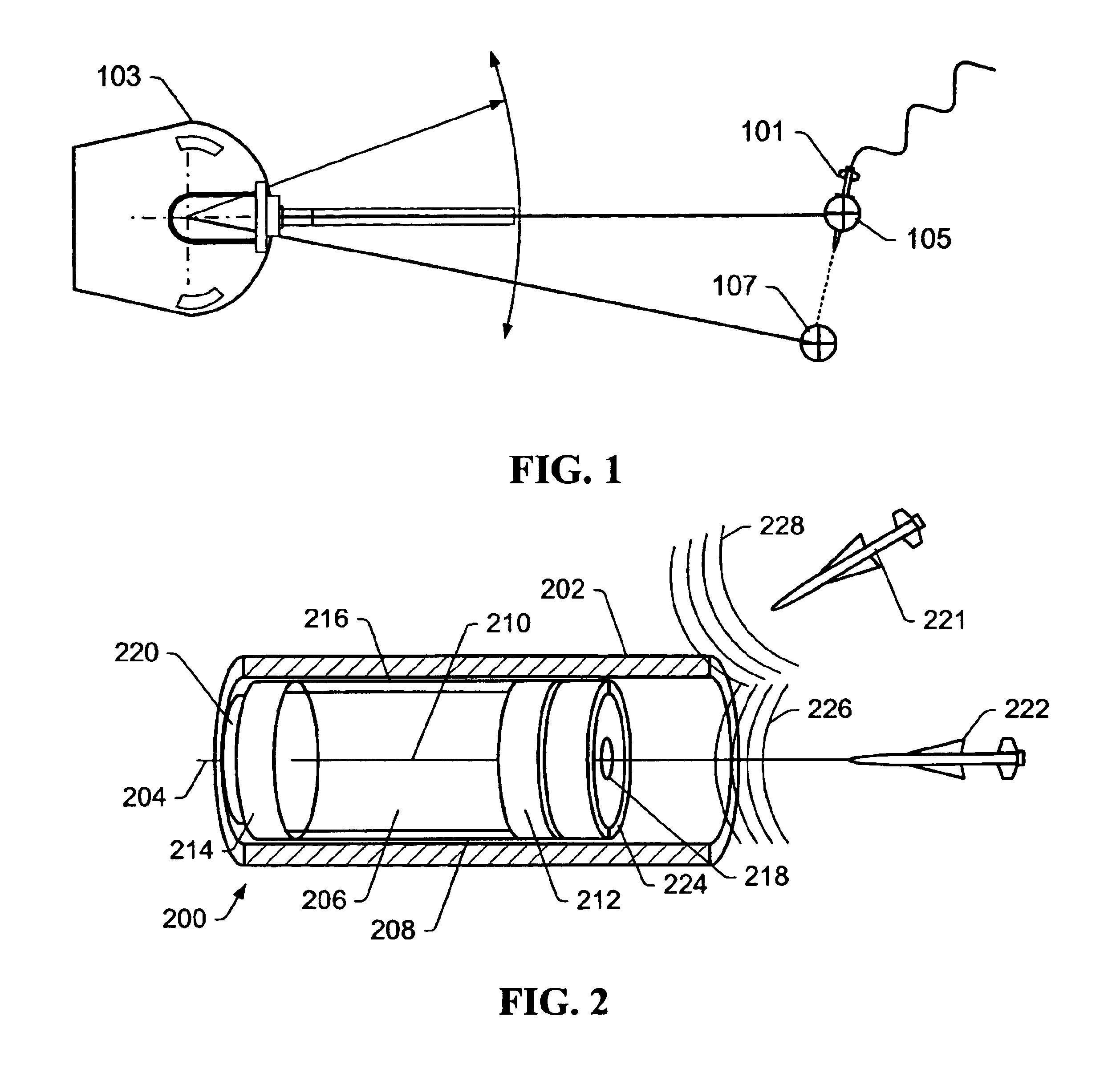
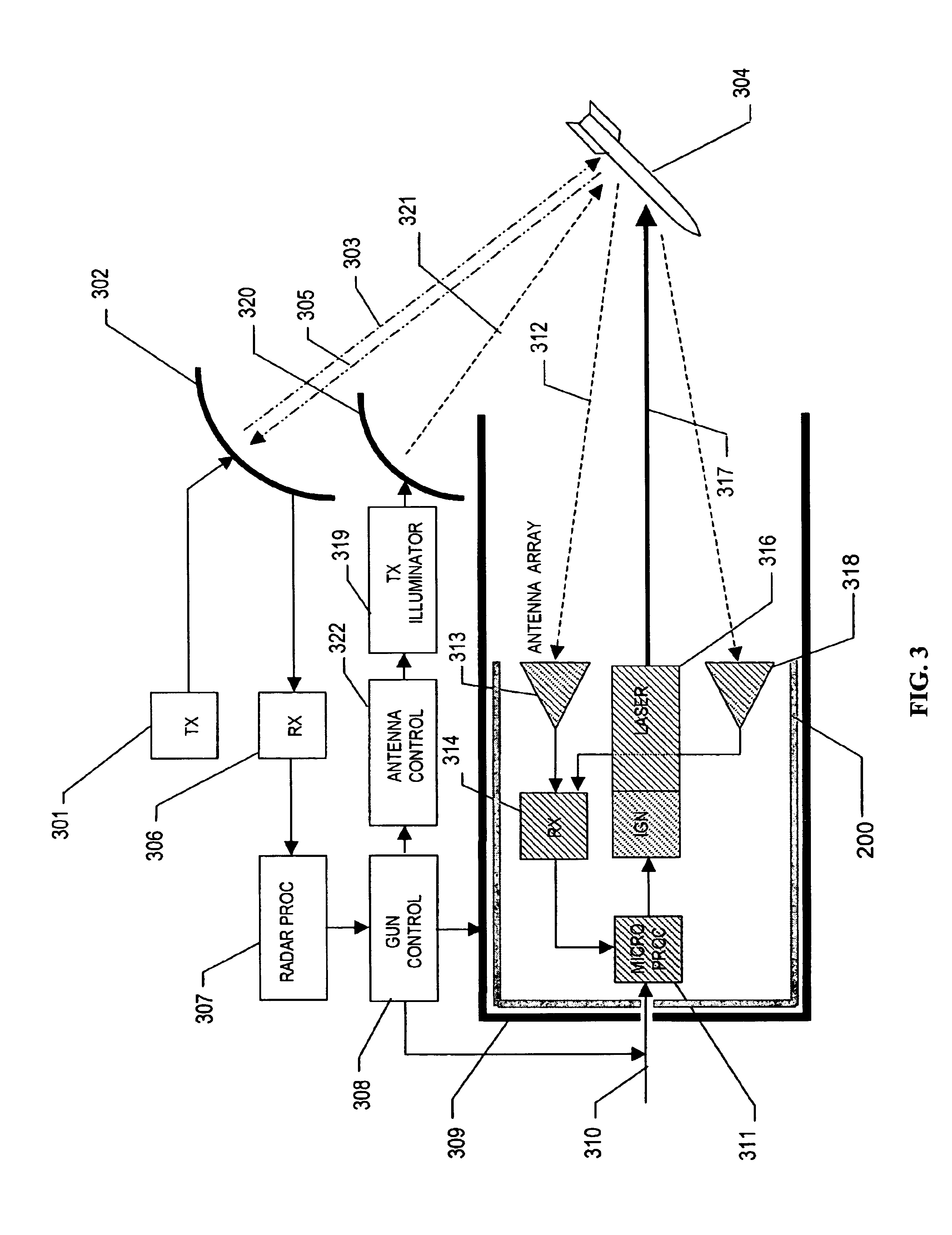
"The patent text describes a laser weapon cartridge that can be used in conjunction with existing weapon systems, such as ballistic guns. The laser weapon cartridge includes a body that fits within the barrel of the gun and includes a laser that can be fired upon firing the gun. The laser can be a high energy laser, such as a chemical oxygen-iodine laser, a hydrogen-fluorine laser, or a deuterium-fluorine laser. The laser weapon cartridge can also include an antenna element or other sensor to detect signals and assess the relative position of a target. The laser weapon cartridge can be programmed and can include a processor to initiate firing of the laser based on certain criteria. The patent text also describes a system that includes a laser weapon cartridge and a gun pointing system that can be used in conjunction with a laser weapon cartridge. The laser weapon cartridge can also be used in conjunction with a hollow elongated member and an aiming system. The patent text also describes a method of aiming the gun barrel towards the target and detecting signals to assess the position of the target."

Problems solved by technology

In modern warfare, low-flying, fast moving and / or maneuvering weapons (e.g., missiles and / or artillery shells) may present a serious threat to military forces.
One of the challenges ballistic anti-missile systems face is time of flight.
The time of flight challenge results from the fact that a projectile directed toward an incoming threat experiences a non-negligible delay from the time the projectile is fired until the distance to the expected target location is covered.
This time of flight delay may make hitting a fast moving and / or maneuvering target particularly difficult.
However, in its tested configuration the THEL system is very large.
Deploying such a large system may be a significant burden for a land-based force.
Issues associated with adding a new laser weapon cartridge to a modern warship may be that the size, weight and / or optical horizon access, required by the mechanical structure necessary for properly pointing and triggering the laser, may bring with it an adverse topside impact.
The cost of such modifications may inhibit such laser systems from being seriously considered for fleet-wide deployment.
The laser may be configured to project a beam of laser light that may initiate and / or promote degradation (e.g., spalling) resulting in catastrophic material failure or other damage.

Method used


Image

  • Radio frequency triggered directed energy munition
  • Radio frequency triggered directed energy munition
  • Radio frequency triggered directed energy munition

Examples


Embodiment Construction

[0045]Embodiments disclosed herein generally relate to laser weapon cartridge systems. Certain embodiments relate to laser weapon cartridge systems that are operatively compatible with existing weapons systems. For example, embodiments may be related to laser weapon cartridge systems compatible with existing ballistic weapons systems. As used herein, a “ballistic weapons system” generally refers to a weapons system capable of firing a projectile or missile. As used herein, “projectile” and “missile” are used interchangeably to refer to an object that is either externally propelled (e.g., a bullet or artillery shell) or self-propelled (e.g., a rocket).

[0046]FIG. 1 depicts an embodiment of a laser weapon cartridge in a ballistic weapons system 103 attempting to engage a maneuvering weapon 101. In an embodiment, maneuvering weapon 101 may be assessed to be a threat, and ballistic weapon 103 may be fired at the maneuvering weapon 101 in a direction towards position 107 because it may ne...


PUM


Abstract

A laser weapon cartridge for disabling and / or destroying a target is disclosed. In an embodiment, the laser weapon cartridge may be compatible within a ballistic gun. For example, the laser weapon cartridge may be placed in the breech of a gun and armed by the gun's firing device. The laser weapon cartridge may assess precise alignment of the optical axis of the laser with a target. Precise alignment maybe based on RF energy from the target. RF energy may be detected by an antenna array coupled to the laser weapon cartridge. When alignment of the target with the laser is detected, the laser weapon cartridge may fire a beam of laser light toward the target. In an embodiment, the laser light may be generated by a chemical laser.

Description

BACKGROUND OF THE INVENTION[0001]1. Field of Invention[0002]Embodiments disclosed herein generally relate to directed-energy weapon systems. More specifically, embodiments relate to aiming directed-energy weapons systems.[0003]2. Description of Related Art[0004]In modern warfare, low-flying, fast moving and / or maneuvering weapons (e.g., missiles and / or artillery shells) may present a serious threat to military forces. The success of ballistic anti-missile systems in destroying an inbound threat may vary depending on the nature of the threat. For example, ship-based self-defense systems (e.g., the Aegis Weapon System (AWS) and the Evolved Sea Sparrow Missile (ESSM)), may be challenged by existing sea-skimming, maneuvering anti-ship missile (ASM) threats. One of the challenges ballistic anti-missile systems face is time of flight. The time of flight challenge results from the fact that a projectile directed toward an incoming threat experiences a non-negligible delay from the time the...

Claims


Application Information

Patent Timeline
Patent Type & Authority Patents(United States)
IPC IPC(8): F41B15/00F41A33/02F41H13/00
CPCF41H13/005F41A33/02
Inventor RODRIGUEZ, RAUL D.BARTOS, ANTHONY L.ROBERTSON, RICHARD G.
Owner COMP SCI A OF NV
Learn More