Optical-electric connector

a technology of optical-electric converters and connectors, applied in the direction of coupling device connections, instruments, optical elements, etc., can solve the problems of difficult to precisely position the optical-electric converters in the housing from the bottom end, and achieve the effect of improving the structure of the insulating housing

Inactive Publication Date: 2006-05-16
HON HAI PRECISION IND CO LTD
View PDF16 Cites 8 Cited by
  • Summary
  • Abstract
  • Description
  • Claims
  • Application Information

AI Technical Summary

Benefits of technology

[0008]It is an object of the present invention to provide an optical-electric connector with an improved structure of insulative housing which can easily and precisely position an optical-electric converter therein.

Problems solved by technology

A problem has been found when the basic structure of the low profile connector disclosed in the above-mentioned patent is applied to the high profile design.
The problem is that if the optical-electric connector is straightly mounted on a printed circuit board, it's difficult to insert and precisely position the optical-electric converter into the housing from a bottom end.

Method used


Image

  • Optical-electric connector
  • Optical-electric connector
  • Optical-electric connector

Examples


Embodiment Construction

[0016]Reference will now be made to the drawing figures to describe the present invention in detail.

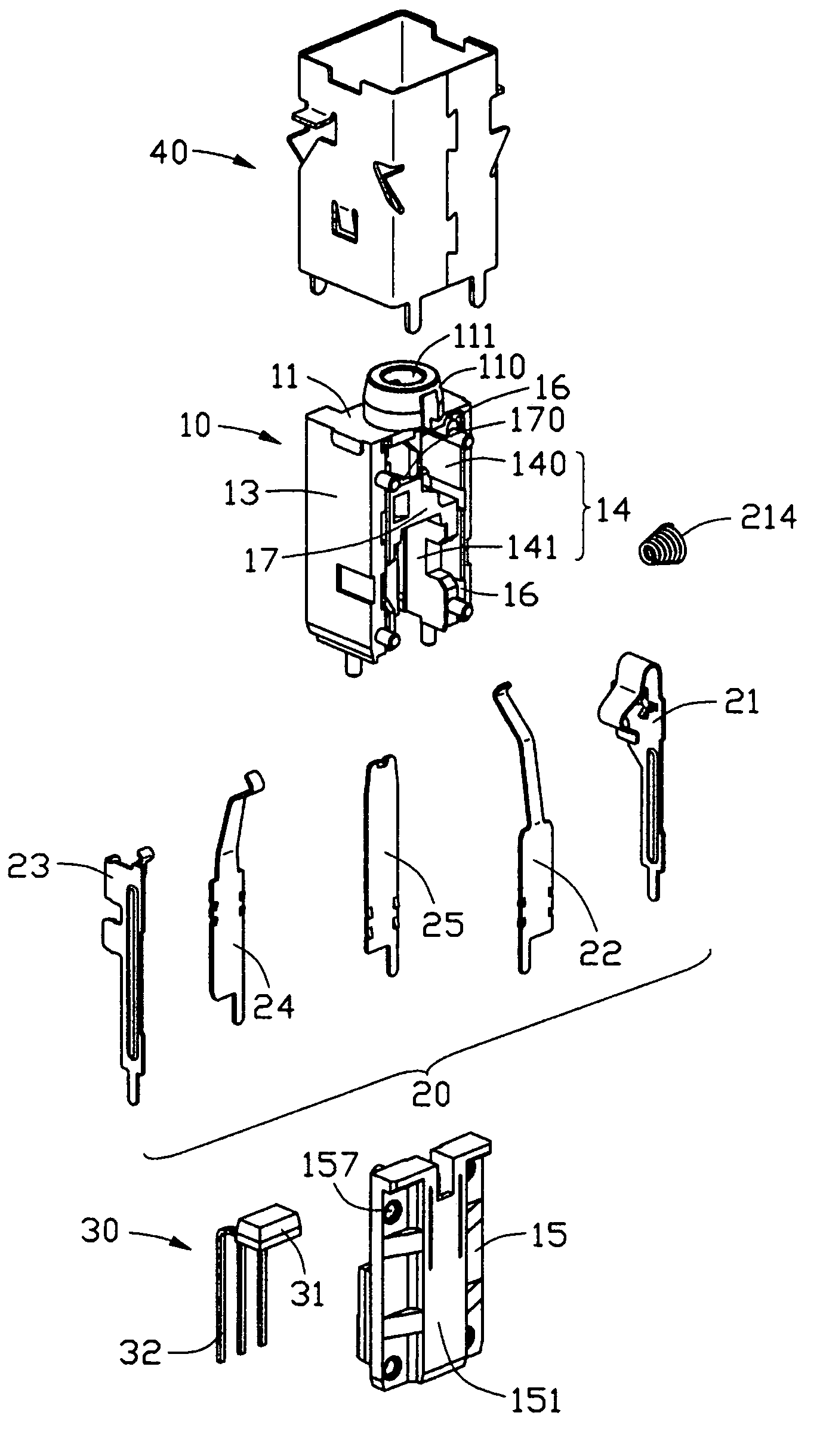
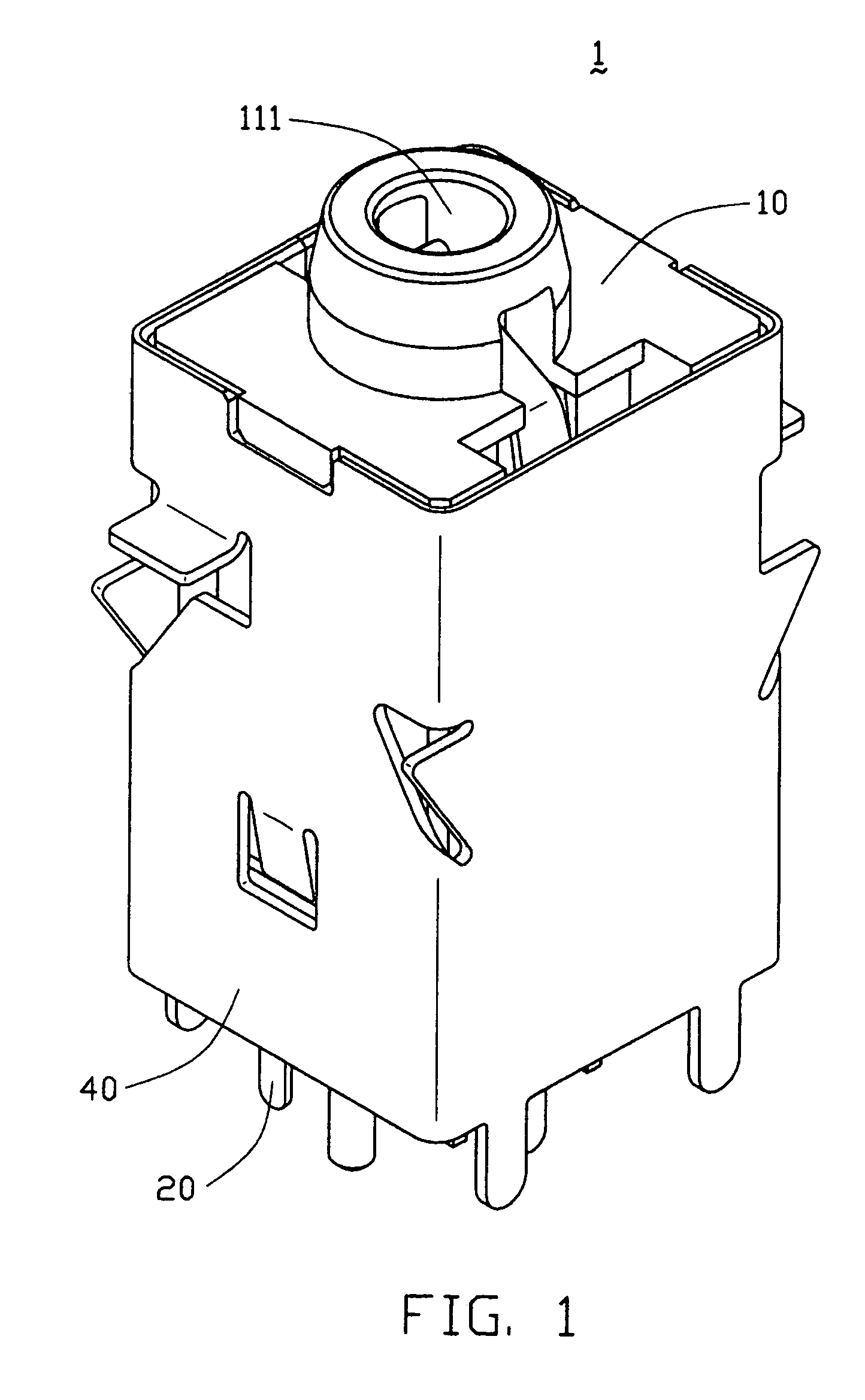
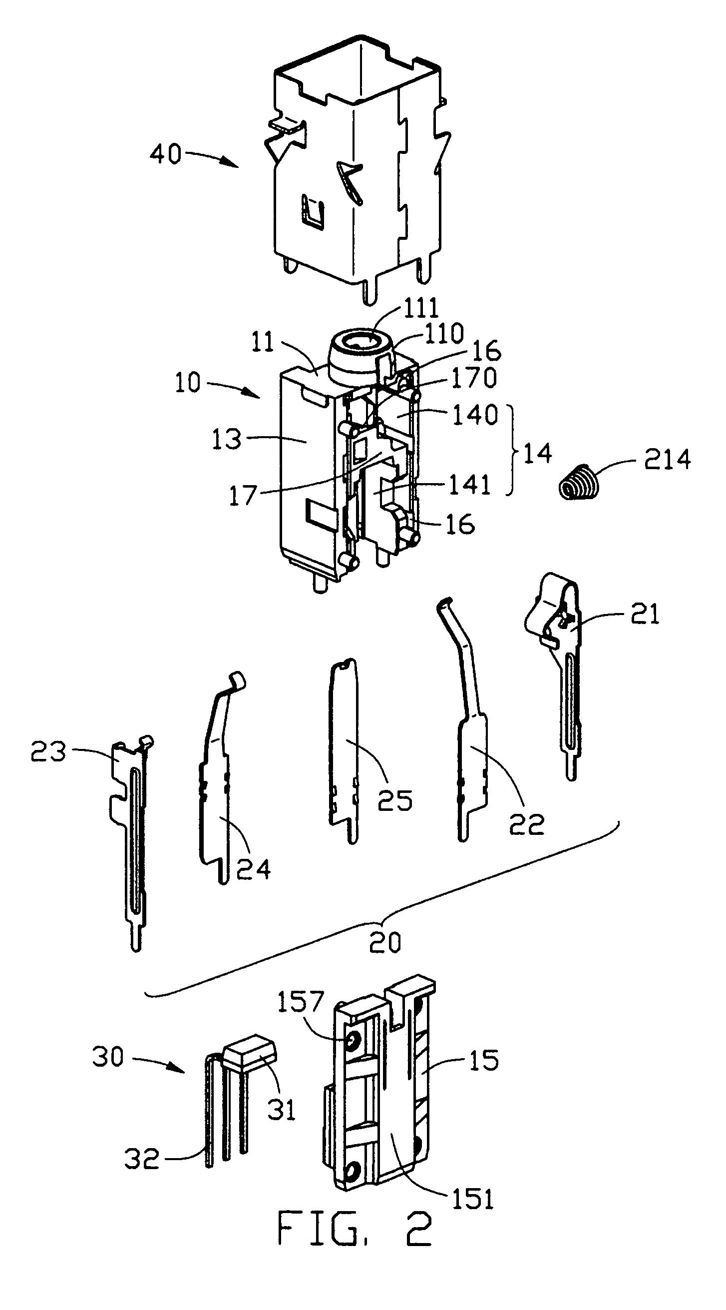
[0017]With reference to FIGS. 1 to 4, an optical-electric connector in accordance with the present invention is a straight-shaped jack connector 1 and comprises an insulating housing 10, a plurality of contacts 20, a spacer 15, an optical-electric converter 30 and a metal shielding 40 enclosing the housing 10.

[0018]The insulative housing 10 is straight-shaped and comprises a mating portion 11, a mounting portion 12, three side portions 13 connecting the mating and mounting portion 11, 12, and a receiving space 14. The housing 10 defines a plurality of passageways 16 for receiving the contacts 20. Four guiding posts 18 are provided on rear edges of two side portions 13. A front side portion 13 defines a plurality of recesses 19.

[0019]The mating portion 11 of the insulative housing 10 forms a cylinder-shaped mating end 110 defining a plug receiving opening 111 extending through the mati...


PUM


Abstract

An optical-electric connector (1) has an insulative housing (10), a number of contacts (21, 22, 23, 24, 25) received in the housing, a spacer (15) and an optical-electric converter (30) assembled in the housing. The housing defines a receiving space (14) for receiving a mating plug and a plurality of passageways (16) for receiving the contacts. The spacer is installed in a rear side of the insulative housing for covering the receiving space. The spacer has a supporting body formed at an inner wall thereof for accommodating the optical-electric converter thereon.

Description

CROSS-REFERENCE TO RELATED APPLICATIONS[0001]This application is related to contemporaneously filed application entitled “OPTICAL-ELECTRIC CONNECTOR”, which is invented by the same inventor and assigned to the same assignee as this application.BACKGROUND OF THE INVENTION[0002]1. Field of the Invention[0003]The present invention generally relates to a connector, and particularly relates to an optical-electric connector which can selectively mate with an electric plug or an optical fiber plug.[0004]2. Description of Prior Arts[0005]U.S. Pat. No. 6,238,249 discloses an optical-electric connector comprising an insulative housing, an optical-electric converter assembled in the housing, which receives and transmits an optical signal from / to the optical plug when the optical plug is connected to the optical-electric connector, and a plurality of terminals received in the housing.[0006]A problem has been found when the basic structure of the low profile connector disclosed in the above-ment...

Claims


Application Information

Patent Timeline
Patent Type & Authority Patents(United States)
IPC IPC(8): H01R24/04H01R24/58G02B6/42
CPCG02B6/4292G02B6/4277
Inventor HAN, HONGQIANGZHANG, GUOHUAZHU, ZIQIANG
Owner HON HAI PRECISION IND CO LTD
Why Eureka
Try Eureka