Video camera

Inactive Publication Date: 2006-05-16
CANON KK
View PDF37 Cites 76 Cited by
  • Summary
  • Abstract
  • Description
  • Claims
  • Application Information

AI Technical Summary

Benefits of technology

[0007]The invention is directed to the solution of the problem of the prior art described above. It is, therefore, an object of the invention to provide a video camera which is capable of solving the problem.

Problems solved by technology

This limitation has presented a problem, because it hinders a desire to make the image plane 906a better viewable by increasing the size of the display part 906.

Method used


Image

  • Video camera
  • Video camera
  • Video camera

Examples


first embodiment

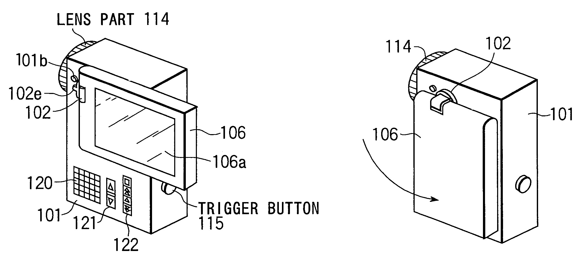
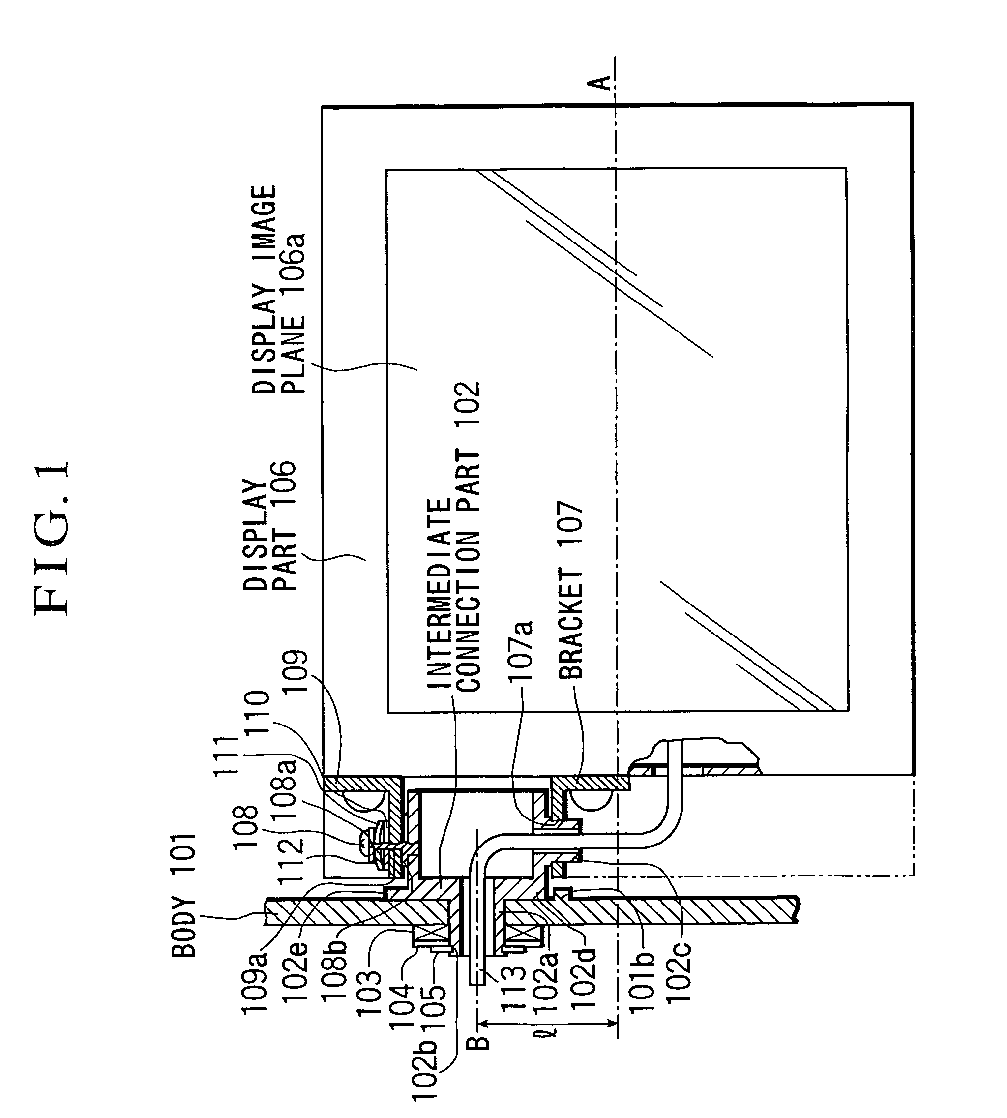
[0054]FIG. 1 is a partly sectional view showing in outline the essential parts of a video camera according to the invention. In FIG. 1, reference numeral 101 denotes a video camera body. An intermediate connection part 102 has a cylindrical part 102a rotatably fitted in a hole provided in the video camera body 101. The intermediate connection part 102 pierces through a washer 103 and a belleville (spring) washer 104 and has a retaining ring 105 secured to a groove part 102b in a state of compressing the belleville washer 104. The body 101, the intermediate connection part 102 and the washer 103 respectively have their abutting faces smoothly formed to be slidable relative to each other.

[0055]A display part 106 has a display image plane 106a on its front side. A first bracket 107 is secured with a screw to a side face of the display part 106 and has a hole part 107a rotatably fitted on a second cylindrical part 102c of the intermediate connection part 102.

[0056]An opening-and-closing...

second embodiment

[0069]FIG. 12 is a block diagram showing the arrangement of the video camera according to the invention. Referring to FIG. 12, a lens part 201 is arranged to obtain an optical image of a shooting object. An image sensor 202 is arranged to photo-electrically convert the image of the shooting object coming from the lens part 201 into an electrical signal. A control part 208 is composed of a CPU, etc. and is arranged to perform control over the whole video camera. A camera signal processing part 203 is arranged to form a luminance signal and color-difference signals by matrix-processing the signal coming from the image sensor 202 and to carry out, on these signals, such processing actions that include a gamma correction process, A / D conversion, etc.

[0070]An image storing part 204 is composed of a magnetic tape or a semiconductor memory and is arranged to store the signals processed by the camera signal processing part 203. The display part 207 has a display image plane of an approximat...

third embodiment

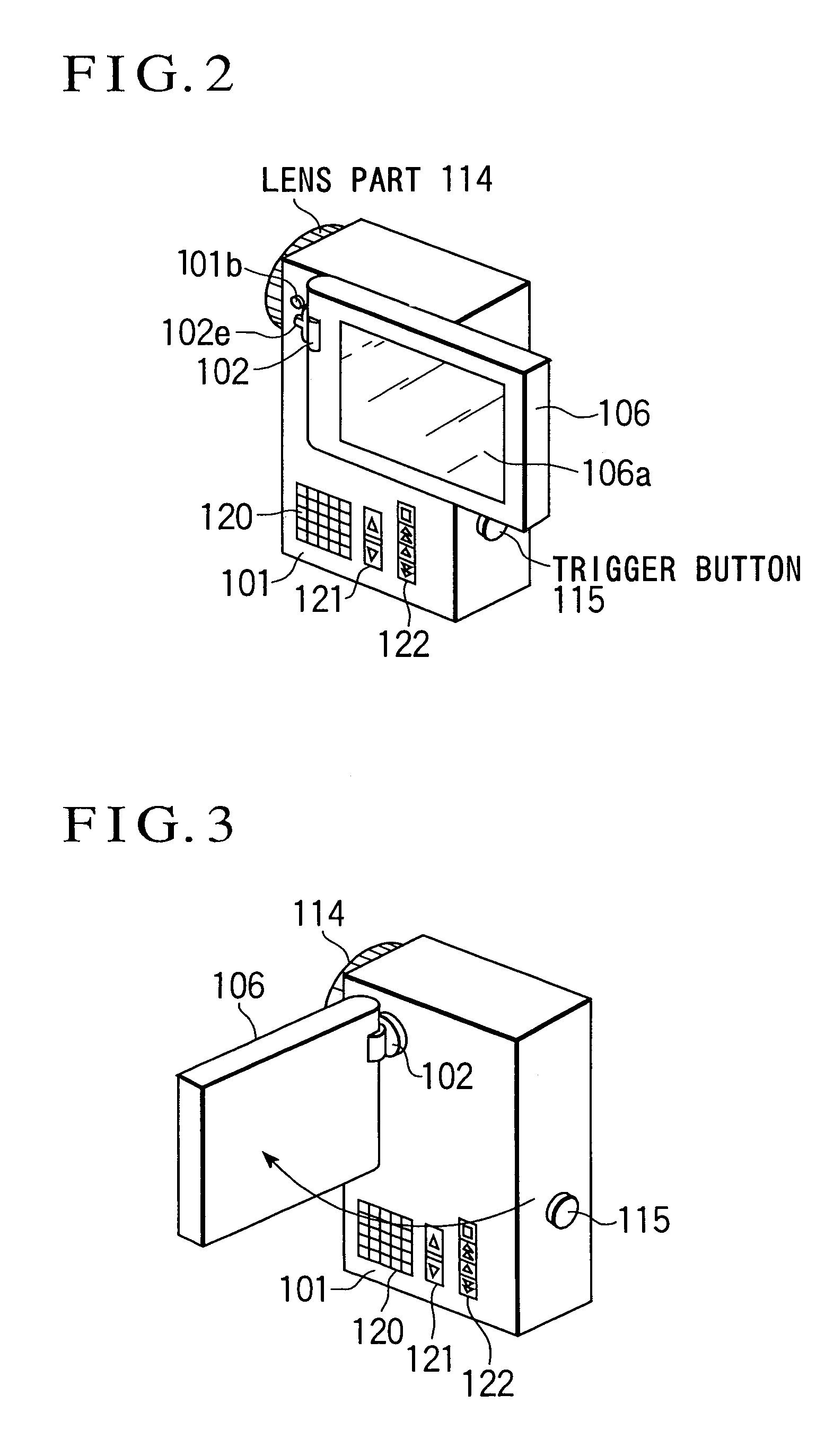
[0080]FIGS. 16(a) and 16(b) and FIG. 17 are simplified perspective views of a video camera according to the invention.

[0081]FIGS. 16(a) and 16(b) show the video camera according to the third embodiment in a state obtained during a shooting operation. The video camera is shown as viewed from a point located obliquely in front of the video camera in FIG. 16(a) and as viewed from a point located obliquely in rear of the video camera. The body of the video camera has a rectangular shape extending longer in the direction of height. A display part 307 which is composed of an LCD or the like is arranged to be stowed along one side face of the video camera body, which is in a rectangular parallelepiped shape extending longer in the direction of height. In the case of the third embodiment, the aspect ratio of the display image plane of the display part 207 is set reverse to the conventional aspect ratio. Incidentally, the aspect ratio of the display image plane is set to 4:3. A lens part 301...


PUM


Abstract

In disposing a display part, such as an LCD panel, on a side face of the body of a compact video camera of a rectangular parallelepiped shape extending longer in the direction of height for use as a viewfinder as well as for a reproduction display, an attempt to minimize the whole size of the video camera for improvement in portability severely limits the size of a major side of the display part, preventing the display image plane from having an easily viewable size. To solve this problem, an intermediate connection part disposed between the video camera body and the display part is arranged to enable the display part to rotate in opening and closing directions with respect to the video camera body and also to rotate in directions included in a plane at which the display part is connected to the video camera body. Further, the axis of rotation of the intermediate connection part with respect to the video camera body is arranged to deviate a predetermined distance from the center line of a minor side of the display part.

Description

BACKGROUND OF THE INVENTION[0001]1. Field of the Invention[0002]The present invention relates to a video camera having a display part such as an LCD or the like arranged to display a picked-up image such as a still image or a motion image.[0003]2. Description of Related Art[0004]Some of video cameras have heretofore been provided with display parts such as liquid crystal displays (LCDs) or the like which are arranged as shown in FIG. 8 for the purpose of viewing a picked-up image. Further, video cameras of the kind having their bodies formed in a rectangular parallelepiped shape extending longer in the direction of height have become popular, because this shape is easily graspable and operatable. FIG. 7 is a perspective view showing by way of example the appearance of a video camera having such a body shape.[0005]As shown in FIG. 7, the video camera includes a video camera body 901, a display part 906 composed of an LCD, etc., having a display image plane 906a, and a lens part 914.[...

Claims


Application Information

Patent Timeline
Patent Type & Authority Patents(United States)
IPC IPC(8): H04N5/222
CPCH04N5/23293H04N5/23216H04N23/531H04N23/62H04N23/631
Inventor KOBAYASHI, JUNJINARITA, HITOSHITAMURA, KYOJI
Owner CANON KK
Why Eureka
Try Eureka