Magnetoresistive effective element, thin film magnetic head, magnetic head device and magnetic recording/reproducing device

a technology of effective elements and magnetic fields, applied in special recording techniques, instruments, nanoinformatics, etc., can solve problems such as spawning of asymmetry fluctuation and unstable output of gmr elements

Active Publication Date: 2006-05-16
TDK CORPARATION
View PDF22 Cites 25 Cited by
  • Summary
  • Abstract
  • Description
  • Claims
  • Application Information

AI Technical Summary

Benefits of technology

[0013]It is an object of the present invention to provide a MR element, a thin film magnetic head, a magnetic head device and a magnetic recording / reproducing device which are unlikely to suffer from the change in magnetization of a magnetic shielding film.
[0017]As mentioned above, the MR element includes the MR film, which is preferably made of a GMR film. A SV film and a TMR film are exemplified as the GMR film. The GMR film includes a free layer, so Barkhausen noise in the free layer must be suppressed. Since the MR element includes the magnetic domain-controlling films which are disposed at both sides of the GMR film in the width direction, respectively, the magnetic domain of the free layer can be controlled by the magnetic domain-controlling films. As a result, the Barkhausen noise can be suppressed.
[0019]The MR element includes the antiferromagnetic films to satisfy the characteristic structural requirement. The antiferromagnetic films are formed in between the first magnetic shielding film and the second magnetic shielding film, adjacent to and bonded through exchange interaction with at least one of the shielding magnetic films. Therefore, the magnetization of the shielding film bonded with the antiferromagnetic film through exchange interaction can be stabilized, to render the reproducing output stable and suppress the asymmetry fluctuation which suffer from the change in magnetization of the shielding film. The change in magnetization of the shielding film is originated from the magnetic field generated from a magnetic recording medium, the recording magnetic field, the magnetic field generated from sense current in the GMR film, and the like. According to the present invention, therefore, the MR element can not be affected by the disturbance due to these magnetic fields.

Problems solved by technology

As a result, the reproducing output of the GMR element may become unstable and asymmetry fluctuation may be spawn.

Method used


Image

  • Magnetoresistive effective element, thin film magnetic head, magnetic head device and magnetic recording/reproducing device
  • Magnetoresistive effective element, thin film magnetic head, magnetic head device and magnetic recording/reproducing device
  • Magnetoresistive effective element, thin film magnetic head, magnetic head device and magnetic recording/reproducing device

Examples


Embodiment Construction

1. MR element

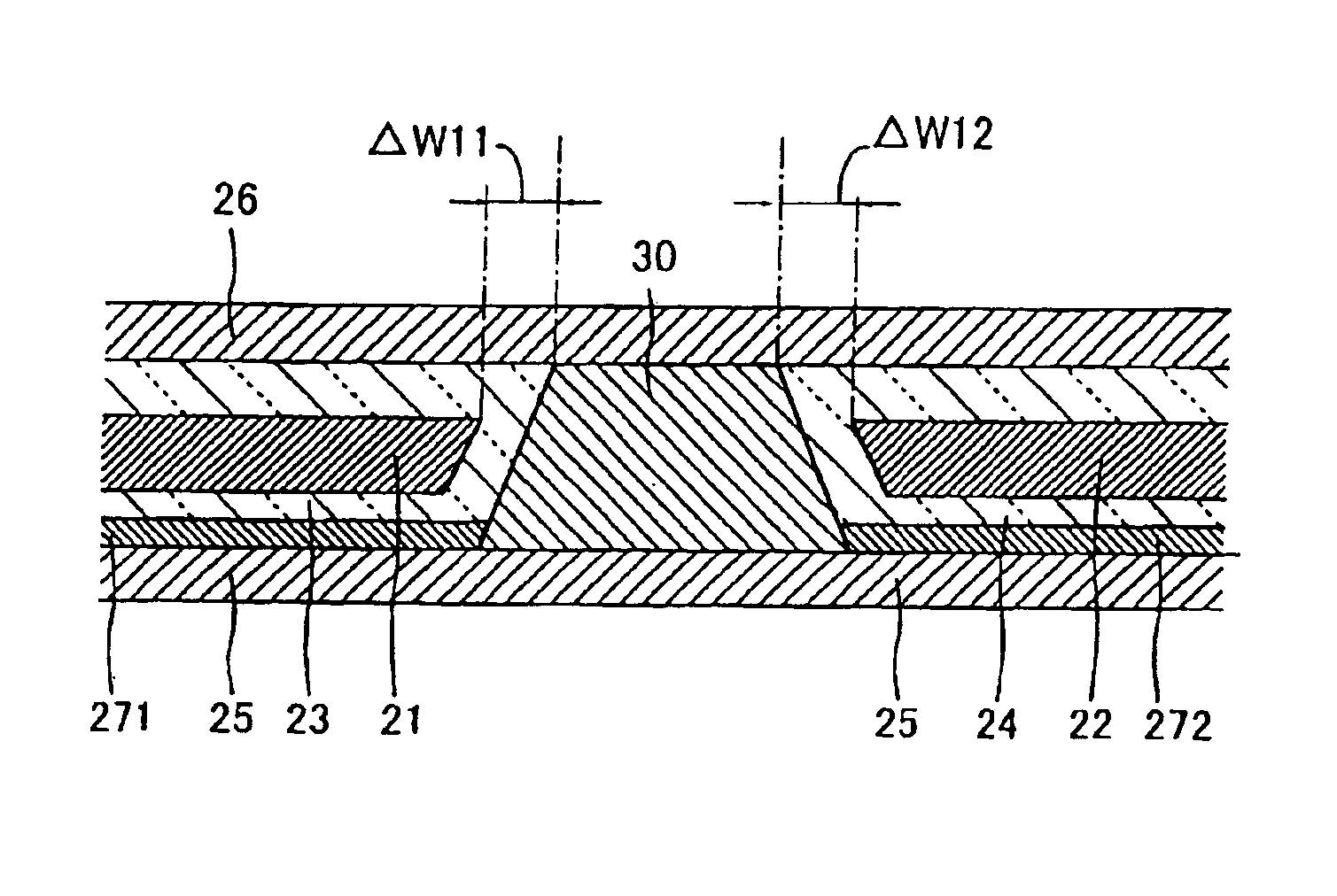
[0037]FIG. 1 is a cross sectional view showing a MR element according to the present invention. The illustrated MR element includes a GMR film 30, magnetic domain-controlling films 21 and 22, a first magnetic shielding film 25, a second magnetic shielding film 26, and antiferromagnetic films 271 and 272. The GMR film 30 includes a free layer (not shown) to respond to external magnetic field, and the magnetic domain-controlling films 21 and 22 are disposed at both sides of the GMR film 30 in the width direction, respectively, to control the magnetic domain of the free layer of the GMR film 30.

[0038]In this embodiment, the magnetic domain-controlling films 21 and 22 are made of hard magnetic film (magnet) such as CoCrPt and CoPt. The films 21 and 22 may be made of antiferromagnetic film. The thickness of the films 21 and 22 is preferably set within 15-60 nm.

[0039]The first magnetic shielding film 25 is disposed on one surface of the GMR element 30 in the thickness directi...


PUM


Abstract

A first magnetic shielding film is disposed on one surface of a magnetoresistive effective film in a thickness direction thereof, and a second magnetic shielding film is disposed on the other surface of the magnetoresistive effective film in said thickness direction thereof. The antiferromagnetic films are disposed in between the first magnetic shielding film and the second magnetic shielding film, adjacent to and bonded through exchange interaction with at least one of the first magnetic shielding film and the second magnetic shielding film.

Description

BACKGROUND OF THE INVENTION[0001]1. Field of the Invention[0002]This invention relates to a magnetoresistive effective element, a thin film magnetic head, a magnetic head device and a magnetic recording / reproducing device.[0003]2. Related Art Statement[0004]With the rapid advance in high density recording for hard disks (HDDs), performances of thin film magnetic heads have been enhanced on vast researches and developments and then, follow the high density recording performances of the HDDs. As the thin film magnetic head is usually employed a composite type thin film magnetic head comprised of a reading element made of a magnetoresistive effective element (hereinafter, called as a “MR element”) and a writing element made of an inductive type electromagnetic conversion element.[0005]The MR element is mainly composed of a giant magnetoresistive effective film (hereinafter, called as a “GMR film”) such as a spin valve film (hereinafter, called as a “SV film”) and a ferromagnetic tunnel...

Claims


Application Information

Patent Timeline
IPC IPC(8): G11B5/127G11B5/00G11B5/39H01F10/16H01F10/32H01F41/30H01F41/32H01L43/08
CPCB82Y10/00B82Y25/00B82Y40/00G11B5/3903G11B5/3909H01F41/32G11B5/3967H01F41/302G11B5/3932G11B2005/0008G11B2005/0016
Inventor TERUNUMA, KOICHI
Owner TDK CORPARATION
Why Eureka
Try Eureka