
System and method for fabricating Bragg gratings with overlapping exposures

Inactive Publication Date: 2006-05-16
PROXIMON FIBER SYST
View PDF7 Cites 34 Cited by
  • Summary
  • Abstract
  • Description
  • Claims
  • Application Information

AI Technical Summary

Benefits of technology

[0008]The invention presents a novel method for fabrication of advanced fiber Bragg gratings, and enabling sequential writing. As opposed to prior art methods, this scheme uses a continuous wave UV laser source and allows for a very precise control and repetitivity of the formation of gratings and subgratings. Furthermore, the inventive method makes it possible to use high average irradiances without destroying the fiber, resulting in a dramatic shortening of fabrication times for complex gratings.
[0014]Further, the interference pattern is preferably reversed a distance approximately being equal to an integer multiplied by the distance between adjacent fringes in the interference pattern. Hereby, the subgratings are synchronized with each other. However, it is also possible to reverse the interference pattern a distance approximately being equal to an integer multiplied by the distance between adjacent fringes in the interference pattern, but with a predetermined offset. Such an offset could be made in real-time, and provides the possibility of introducing precisely controlled advanced properties such as chirp, phase shifts and apodization.
[0016]The translation of the interference pattern is preferably performed by means of a controlled variation of a phase shift between the interfering beams. This enables a very precisely controlled translation of the interference pattern, with few mechanically moving parts.
[0018]With this apparatus, the method discussed above could be executed. Accordingly, a novel apparatus is presented, preferably based on sequential writing, for fabrication of advanced fiber Bragg gratings. As opposed to prior art apparatuses, a continuous wave light source is used, which allows for a very precise control and repetitivity of the formation of gratings and subgratings. Furthermore, the inventive apparatus makes it possible to use high average irradiances without destroying the fiber, resulting in a dramatic shortening of fabrication times for complex gratings. Furthermore, the invention provides a major improvement of the grating quality as compared to other sequential methods.

Problems solved by technology

Furthermore, the inventive method makes it possible to use high average irradiances without destroying the fiber, resulting in a dramatic shortening of fabrication times for complex gratings.

Method used


Image

  • System and method for fabricating Bragg gratings with overlapping exposures
  • System and method for fabricating Bragg gratings with overlapping exposures
  • System and method for fabricating Bragg gratings with overlapping exposures

Examples


Embodiment Construction

[0035]Further scope of the applicability of the present invention will become apparent from the detailed description given hereinafter. However, it should be understood that the detailed description and specific examples, while indicating preferred embodiments of the invention, are given by way of illustration only, since various changes and modifications within the spirit and scope of the invention will become apparent to those skilled in the art from this detailed description.

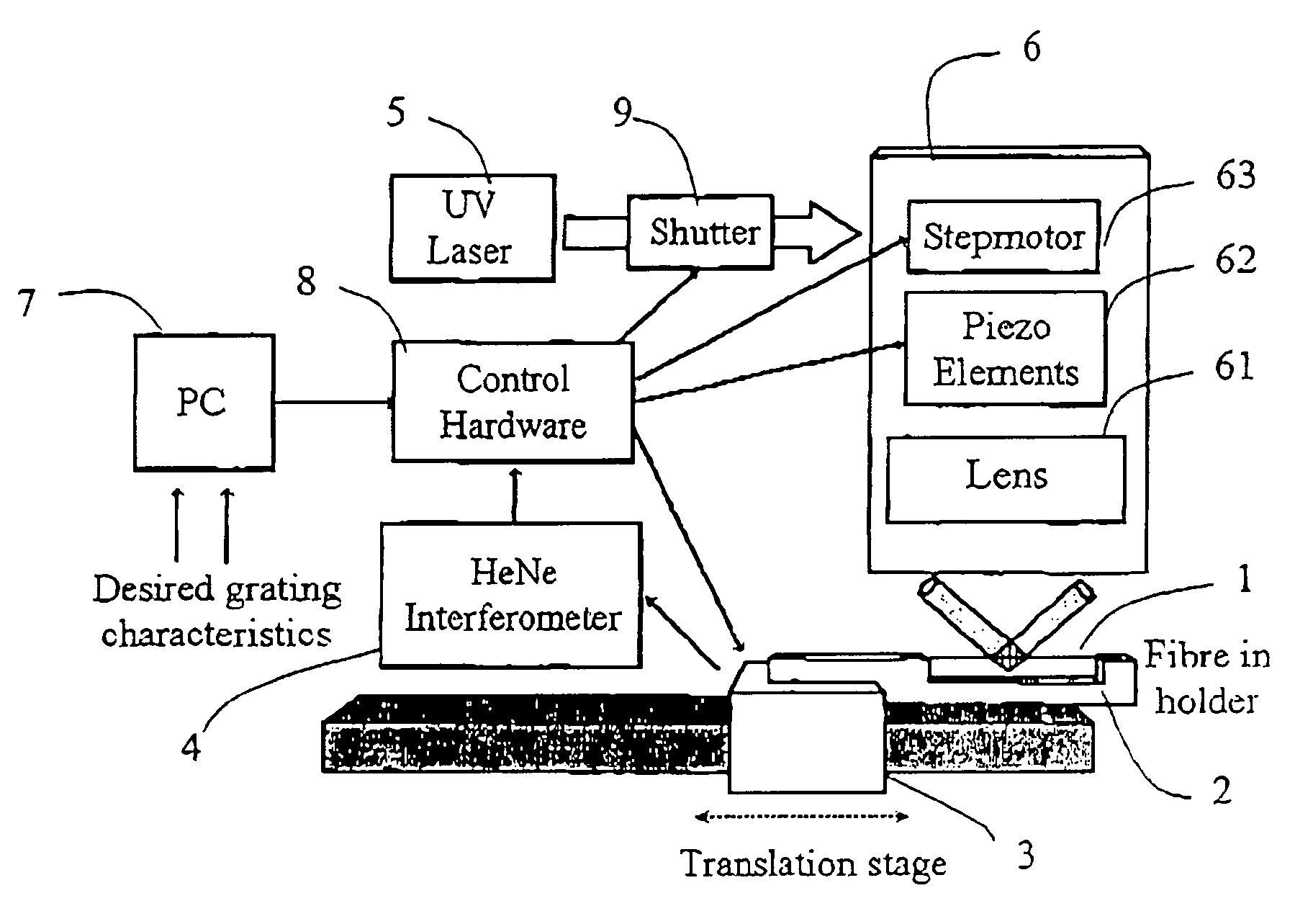
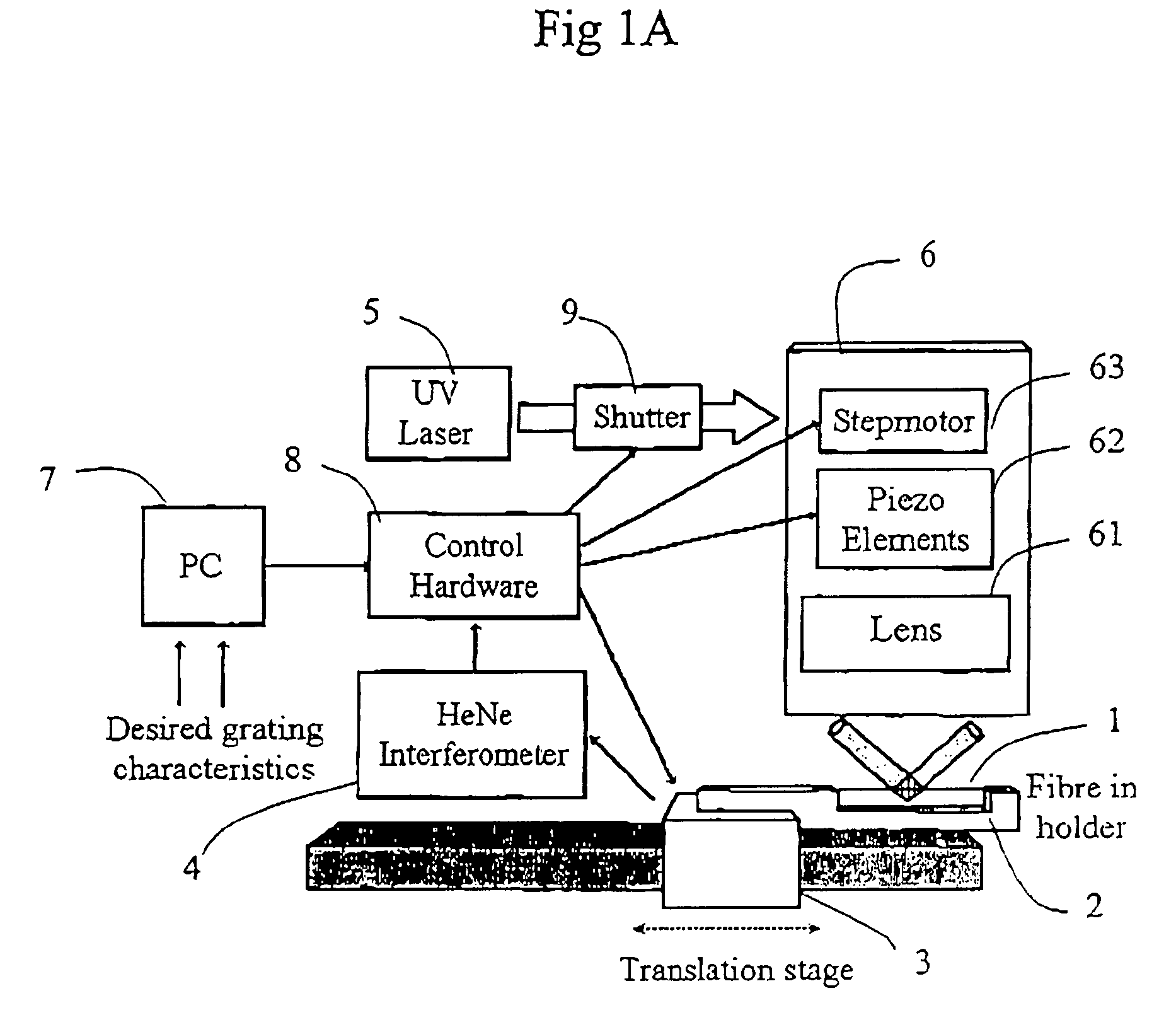
[0036]The setup according to an embodiment of the invention is illustrated in FIG. 1A. A fiber 1 to be exposed is placed in a fiber holder 2 mounted on an airbearing born carriage 3, which is translated by a feedback-controlled linear drive. The position of the translator stage relative the UV interference pattern is measured with a heterodyne interference detection system 4 utilizing a He—Ne laser as light source. The resulting spatial resolution is approximately 0.6 nm, available over the translation length...


PUM


Abstract

A novel method based on sequential writing for fabricating of advanced fiber Bragg gratings is disclosed. As opposed to already presented sequential methods, this scheme uses a continuous wave UV laser source and allows for a very precise control and repetitively of the formation of the gratings. Furthermore, one can use high average irradiances without destroying the fiber, resulting in a dramatical shortening of fabricating times for complex gratings.

Description

FIELD OF THE INVENTION[0001]The present invention relates to a method for photo-inducing a grating in an optical fiber by simultaneously exposing the fiber with two mutually coherent light beams which intersect with an angle and interfere in a predetermined region of the fiber so as to create an interference pattern along a longitudinal axis of the fiber and translating the fiber essentially in the direction of the longitudinal axis. The invention further relates to an apparatus for photo-inducing a grating in an optical fiber comprising a source for emitting light, is a beam splitter for forming two mutually coherent light beams, a fiber holder for holding the fiber during exposure, means for moving the fiber essentially in the direction of a longitudinal axis of the fiber through an exposing area and a projection system for making the beams intersect with an angle in the exposure area and thereby to interfere in a predetermined region of the fiber so as to create an interference p...

Claims


Application Information

Patent Timeline
IPC IPC(8): G02F1/295G02B6/34
CPCG02B6/02133G02B6/02152
Inventor SAHLGREN, BENGTPETERMANN, INGEMAR
Owner PROXIMON FIBER SYST
Learn More