
Neurostimulating lead

a neurostimulation and lead technology, applied in the field of implantable leads, can solve the problems of scarring and significant patient discomfort, limited effectiveness of spinal cord stimulation, and several distinct performance problems of metallic band electrodes, and achieve the effect of being readily steered

Inactive Publication Date: 2006-05-16
ADVANCED NEUROMODULATION SYST INC
View PDF41 Cites 351 Cited by
  • Summary
  • Abstract
  • Description
  • Claims
  • Application Information

AI Technical Summary

Benefits of technology

[0011]Utilizing the manufacturing method described herein, it has been possible to produce neurostimulating leads having an outer diameter of only 0.026 inch (about 2 French) and with an internal lumen diameter of about 0.012 inch, allowing the catheter to be passed over a 0.010 inch guidewire or stylet. The thin film electrodes are typically less than about 250 mic

Problems solved by technology

Spinal cord stimulation, however, has limited effectiveness for certain pain conditions primarily due to limited accessibility to targeted nerves.
However, with existing technology, nerve specific stimulation can only be accomplished with a surgical implant, which results in scarring and significant patient discomfort.
Metallic band electrodes possess several distinct performance problems.
When placed on flexible catheter materials, they add significant stiffness that greatly interferes with the steerability of such catheters.
As such, prior art catheters having band electrodes are often restricted to applications where steerability and selective placement are not required.
In addition, when DC or RF energy is applied to metallic band electrodes, a thermal field is generated which can interfere with energy delivery, increased power consumption and, in blood environments, create potentially life-threatening blood clots.
Finally, the manufacture of catheters utilizing metallic band electrodes is quite labor intensive, resulting in high manufacturing costs.
It is a major limitation of totally implantable systems in that high power consumption necessarily shortens the time between surgeries for battery replacement.
Procedurally, nerve stimulation therapy becomes more challenging when spinal or peripheral nerves of the body are targeted.
Due to the fact that many regions of the body cannot be effectively stimulated via the spinal cord, the only alternative in many cases is to surgically implant electrodes.

Method used


Image

  • Neurostimulating lead
  • Neurostimulating lead
  • Neurostimulating lead

Examples


Embodiment Construction

[0021]The present invention is provides a lead of the type typically used for neurostimulation. The invention is described in the context of a neurostimulating lead as a specific example for illustrative purposes only. The appended claims are not intended to be limited to any specific example or embodiment described in this patent. It will be understood by those skilled in the art that the lead of the present invention may be used for a wide variety of applications with only insubstantial changes to the apparatus and specifications as described below. These applications include, but are not limited to, spinal stimulation, peripheral nerve stimulation, deep brain stimulation, neuromonitoring, cardiac monitoring, cardiac rhythm management, ablation, mapping, or other medical applications using leads.

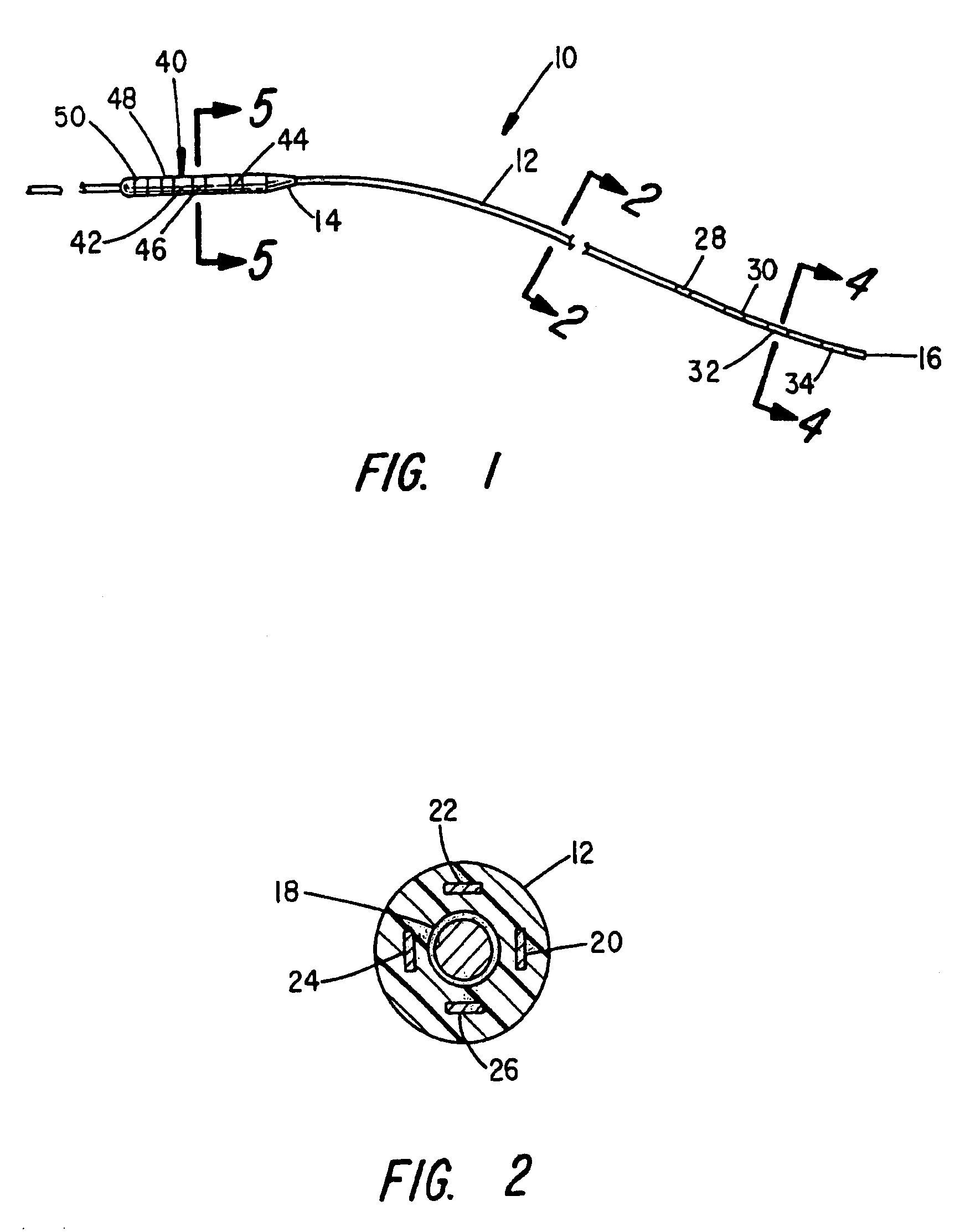
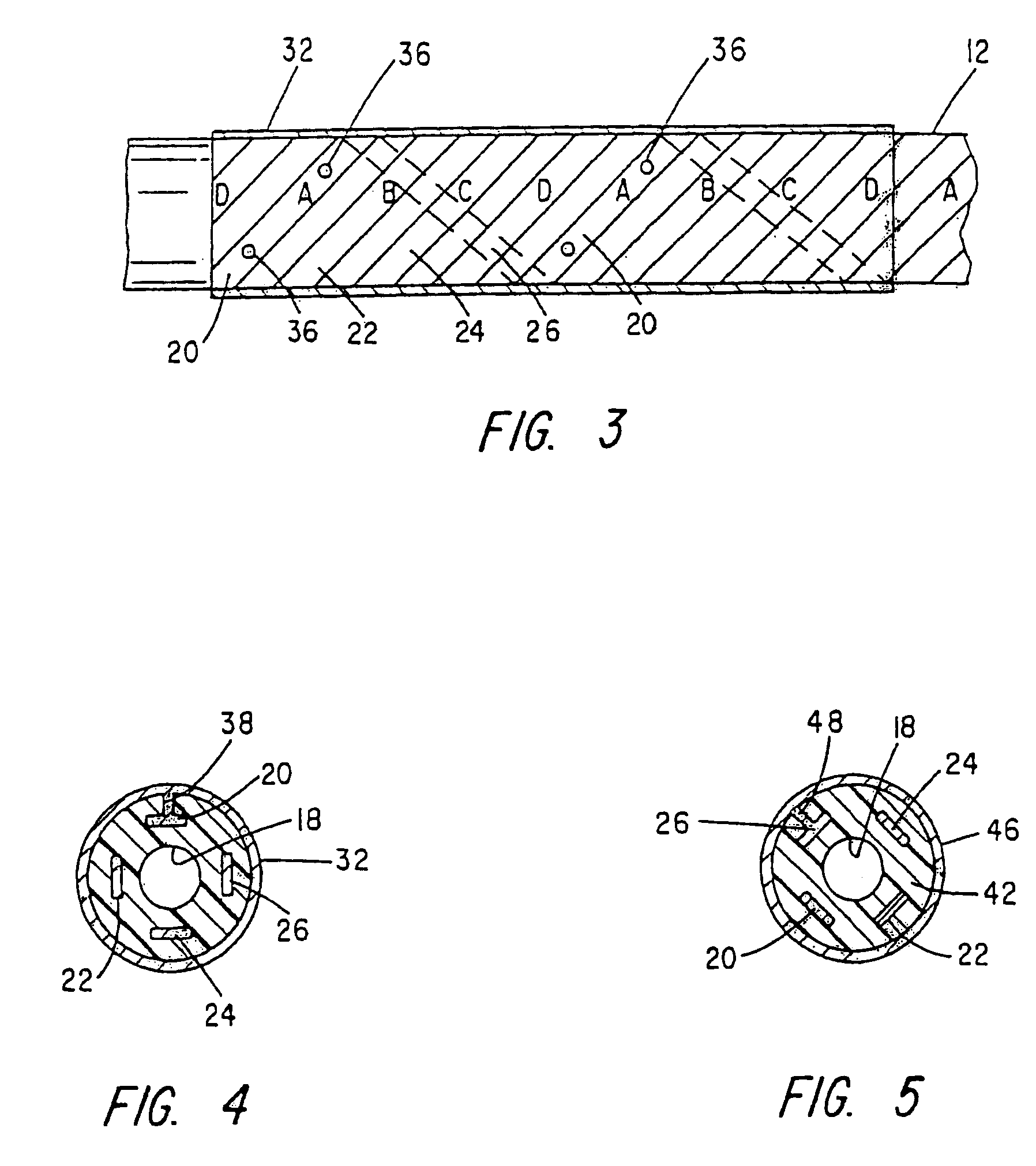
[0022]Referring to FIG. 1, there is indicated generally by numeral 10 a neurostimulating lead constructed in accordance with the present invention. It is illustrated to include an elongate...


PUM

PropertyMeasurementUnit
Lengthaaaaaaaaaa
Lengthaaaaaaaaaa
Thicknessaaaaaaaaaa

Abstract

A neurostimulating lead is provided for use in stimulating the spinal chord, spinal nerves, or peripheral nerves or for use in deep brain stimulation that comprises an elongated, flexible lead having improved steerability properties. The lead includes a plurality of thin-film metal electrodes connected by conductors embedded within the wall of the lead to electrical contacts at the proximal end of the lead. The lead is further designed to include an internal lumen for use with a guidewire in an over-the-wire lead placement.

Description

CROSS-REFERENCE TO RELATED APPLICATIONS[0001]This application is a continuation-in-part of application Ser. No. 09 / 396,961, filed Sep. 16, 1999, now abandoned.BACKGROUND OF THE INVENTION[0002]1. Field of the Invention[0003]This invention relates generally to implantable leads for conducting electrical signals to and / or from a stimulating pulse generator, and more particularly to neurostimulating leads having electrodes adapted for treatment of neurogenic, neuropathic or neuroceptive nerve conditions.[0004]2. Discussion of the Related Art[0005]Conventional neural stimulation therapies rely on electrode catheters for stimulating various regions of the spinal cord that correspond to each physiologic region of the body. Spinal cord stimulation, however, has limited effectiveness for certain pain conditions primarily due to limited accessibility to targeted nerves. In many cases where spinal cord stimulation is inadequate, spinal or peripheral nerves must be specifically stimulated to pr...

Claims


Application Information

Patent Timeline
IPC IPC(8): A61N1/05
CPCA61N1/0551A61N1/0534Y10T29/49002Y10T29/49117Y10T29/49174Y10T29/49176Y10T29/49005
Inventor SCHROM, MARK G.ROBINSON, PAUL J.
Owner ADVANCED NEUROMODULATION SYST INC
Learn More