
Single electrode probe for a cardiac pacemaker system

a single electrode, pacemaker technology, applied in the field of single electrode probes for cardiac pacemakers, can solve the problems of two separate electrode probes that have to be implanted, serious limitations in the stimulation properties, and the inability to place atrial ring electrodes, and achieve the effect of easy introduction

Inactive Publication Date: 2006-05-16
BIOTRONIK MESS UND THERAPIEGERAETE GMBH & CO
View PDF22 Cites 18 Cited by
  • Summary
  • Abstract
  • Description
  • Claims
  • Application Information

AI Technical Summary

Benefits of technology

"The invention is a single electrode probe for improving the hold of electrodes to the atrial myocardium in the heart. The electrode line is divided into two sections, which helps to hold the electrodes in place without complicating the design. The two sections have ring electrodes to improve the hold. The electrode line can also have a stiffening coil of elastic material to bend the line into a predetermined shape when pulled. The electrode line can also have a memory metal element that changes its shape at a triggering temperature to deform the line. The technical effects of the invention are improved hold of electrodes to the atrial myocardium and simplified design of the electrode line."

Problems solved by technology

The main disadvantages thereof however is that two separate electrode probes have to be implanted into the heart and positioned there.
A problem which arises here however is that the atrial ring electrodes are not placed in an established position on the wall but float freely in the blood stream.
These so-called “floating” electrodes in the atrium result in serious limitations in terms of the stimulation properties as generally very high stimulation amplitudes have to be used.
The main reason for this is the lack of on-wall established placement of the floating electrodes.
The high stimulation amplitudes entail the disadvantage of a high level of energy consumption and frequent phrenic stimulation effects.
The relatively complicated configuration of that single electrode probe is found to be a disadvantage in that respect.
In addition using a guide wire in implantation of the single electrode probe is not desirable.
A disadvantage in this arrangement however is that two separate electrode probes have to be implanted.

Method used


Image

  • Single electrode probe for a cardiac pacemaker system
  • Single electrode probe for a cardiac pacemaker system
  • Single electrode probe for a cardiac pacemaker system

Examples


Embodiment Construction

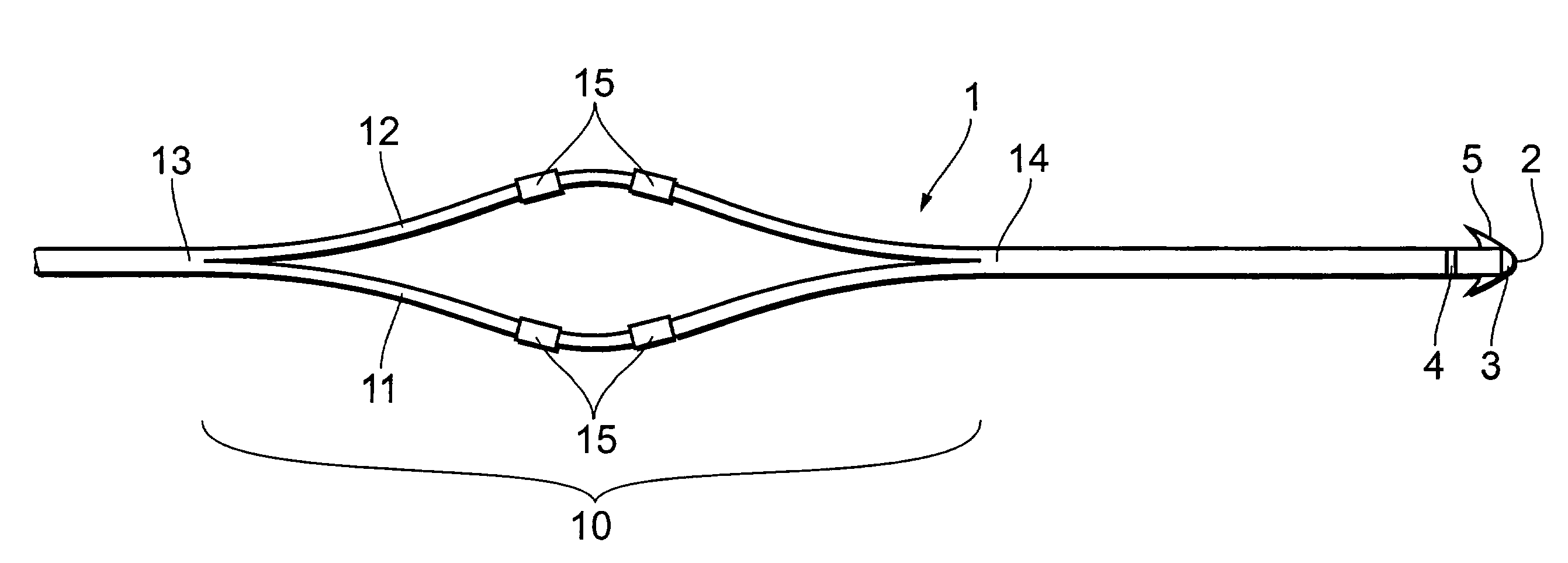
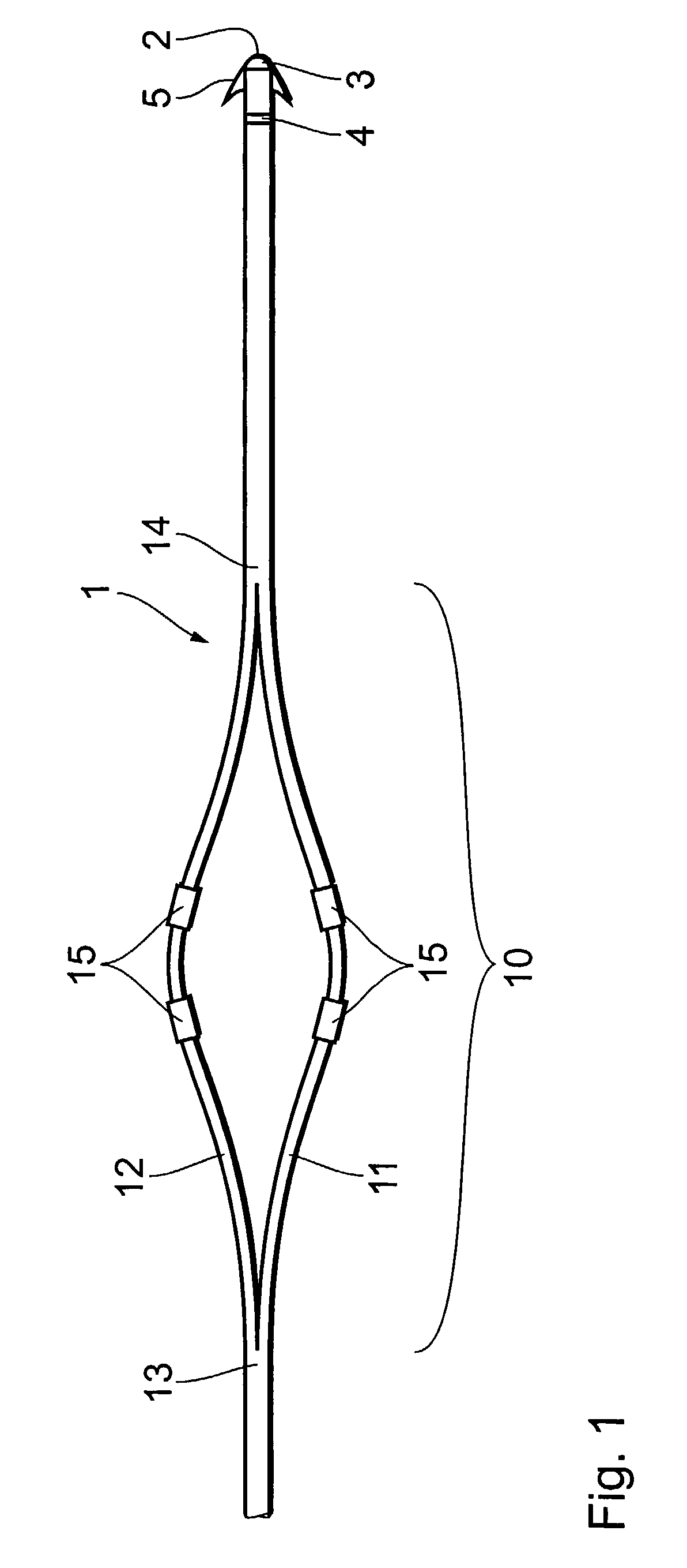
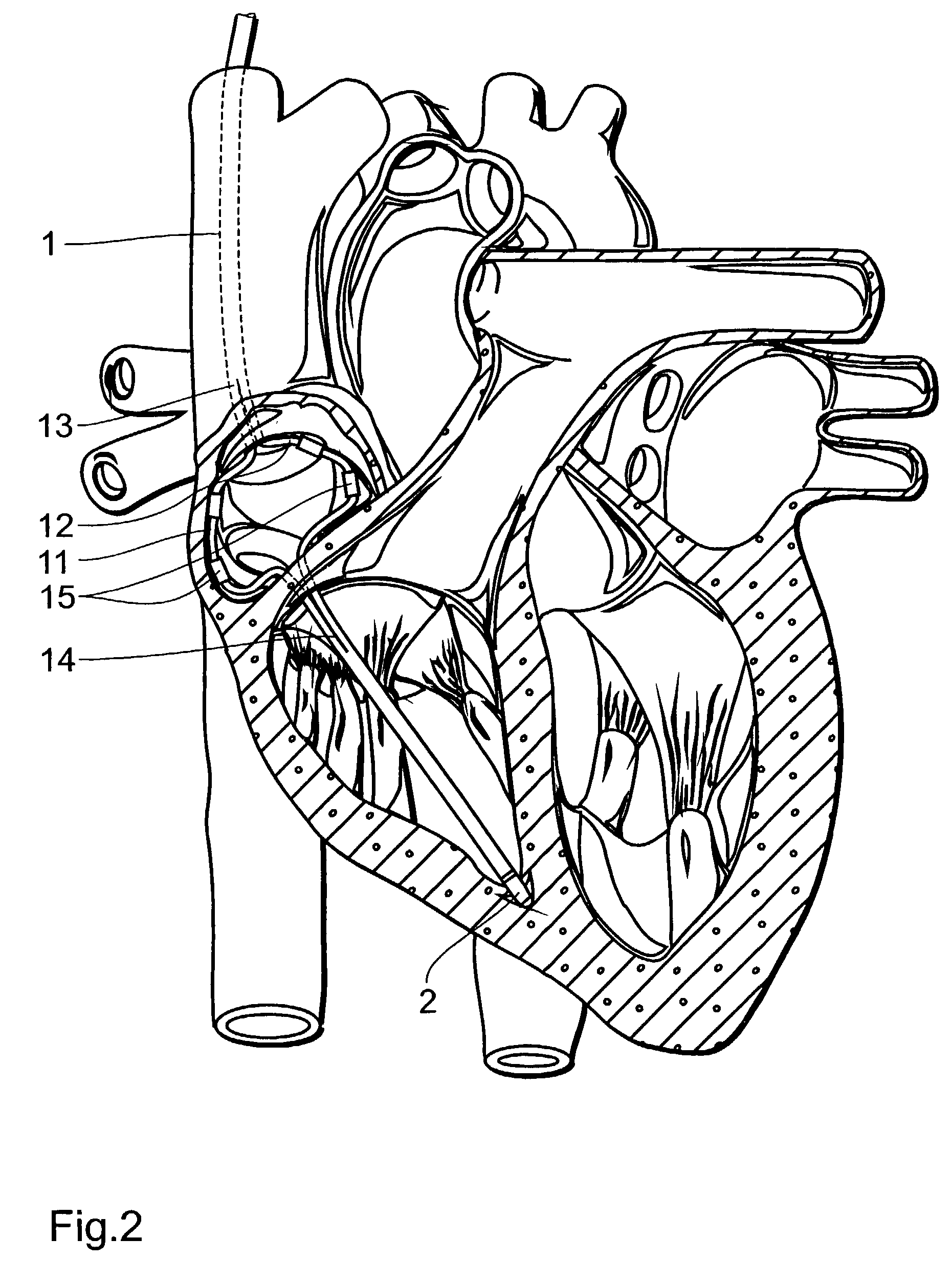
[0020]FIG. 1 shows that section of a single lead electrode line 1 which is intended for placement in a heart. A distal end 2 of the electrode line 1 and the section of the electrode line 1, which is immediately adjoining same, are provided for placement in a ventricle of a heart. For that purpose the electrode line 1 has a tip electrode 3, a ring electrode 4 disposed in the proximity of the tip electrode and so-called tines 5 for anchoring the electrode line in the myocardium of the ventricle.

[0021]The distal section of the electrode line 1 that is provided for placement in the ventricle is adjoined by a section 10 that is provided for placement in the atrium of a heart. In the region of the section 10, the electrode line 1 is divided into two portions 11 and 12. The two portions 11 and 12 are joined at a proximal end 13 of the two-part section 10 to form a single electrode line which for example leads to an implantable pacemaker. At the distal end 14 of the two-part section 10 the ...


PUM


Abstract

A single electrode probe for a cardiac pacemaker system, in particular for a DDD cardiac pacemaker system, has an electrode line with a bifurcated section, at the beginning of which the electrode line divides into two electrode line portions which rejoin at the end of the section to again form one portion, wherein at least one of the portions has at least one electrode for the delivery of electrical energy to adjoining myocardium.

Description

[0001]The invention concerns a single electrode probe for a cardiac pacemaker system, in particular for a DDD cardiac pacemaker system, comprising an electrode line which has a section which is divided into two and at the beginning of which an electrode line portion is divided into two portions which join again at the end of the section to form one portion, wherein at least one of the portions has at least one electrode for the delivery of electrical energy to adjoining myocardium.BACKGROUND OF THE ART[0002]In accordance with knowledge in the cardiac pacemaker art, the use of so-called DDD cardiac pacemaker systems is recommended in relation to appropriate pathological results. That specification “DDD” (Dual pacing / Dual sensing / Demand+Triggered) means that on the one hand stimulation (“pacing”) is effected in both heart chambers and that, on the other hand, innate actions in respect of the sinus or AV node of the heart, which are still present, are detected both in the atrium and al...

Claims


Application Information

Patent Timeline
Patent Type & Authority Patents(United States)
IPC IPC(8): A61N1/05
CPCA61N1/056
Inventor TASKIRAN, MURATFLACH, ERHARD
Owner BIOTRONIK MESS UND THERAPIEGERAETE GMBH & CO
Learn More