Vehicle and method for controlling brake system indicators

a technology of brake system and indicators, which is applied in the direction of braking components, electric devices, gas pressure propulsion mounting, etc., can solve the problems of reducing braking ability, defeating the function of abs controller, and not providing brake pedal feedback to the vehicle operator

Inactive Publication Date: 2006-05-16
FORD GLOBAL TECH LLC
View PDF7 Cites 11 Cited by
  • Summary
  • Abstract
  • Description
  • Claims
  • Application Information

AI Technical Summary

Problems solved by technology

In these vehicles the EHB system may not provide brake pedal feedback to the vehicle operator when the ABS is active—i.e., when the ABS is in use.
This change in feel may prompt the vehicle operator to pump the brake pedal, and thereby defeat the function of the ABS controller and diminish braking ability.

Method used


Image

  • Vehicle and method for controlling brake system indicators
  • Vehicle and method for controlling brake system indicators
  • Vehicle and method for controlling brake system indicators

Examples


Embodiment Construction

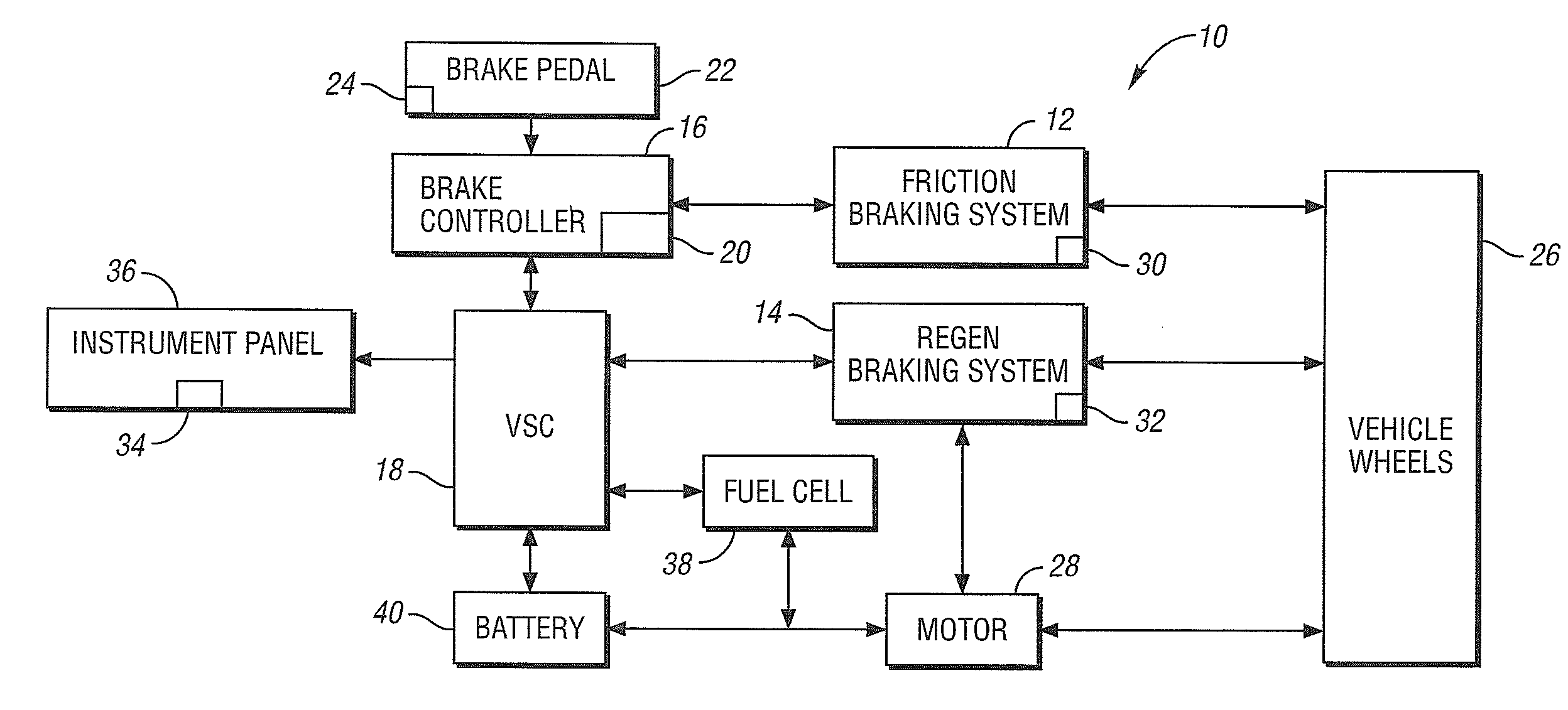
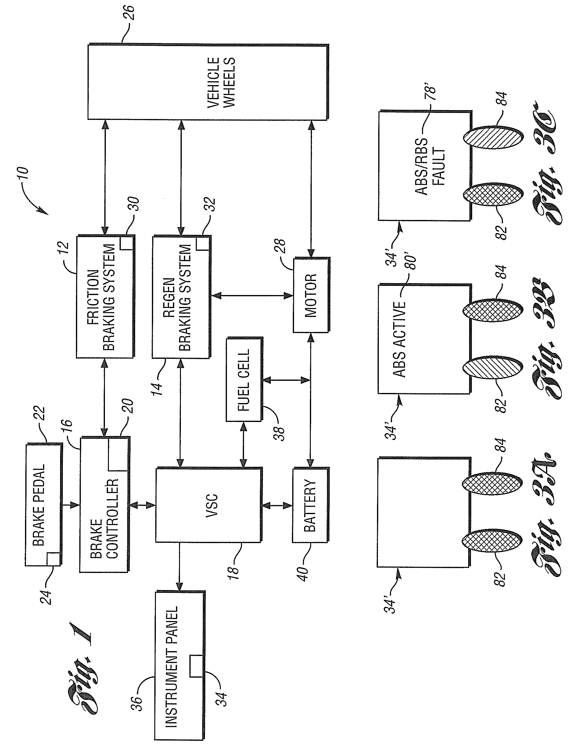
[0019]FIG. 1 shows a simplified schematic diagram of a portion of a vehicle 10 in accordance with the present invention. The vehicle 10 includes a friction braking system 12 and a regenerative braking system (RBS) 14. A brake controller 16 is shown in communication with the friction braking system 12 and a vehicle system controller (VSC) 18. Although a single brake controller is shown in FIG. 1, a vehicle, such as the vehicle 10 may include separate brake controllers for the friction braking system 12 and the RBS 14. Although FIG. 1 shows the brake controller 16 communicating directly with the friction braking system 12, but not the RBS 14, it is understood that the brake controller 16 can communicate with the RBS 14 through the VSC 18. In addition, the VSC 18 may incorporate the brake controller 16, or other controllers, such as a powertrain control module (PCM). Thus, the various systems within the vehicle 10 can be controlled by a single controller, separate software controllers ...


PUM


Abstract

An instrument panel for a vehicle has an anti-lock braking system and a regenerative braking system. A method is used to control the brake system indicators on the instrument panel. If it is determined that an anomalous condition exists in either the anti-lock braking system or the regenerative braking system, a first indicator is illuminated in an amber color to alert the vehicle operator of this condition. If the anti-lock braking system is active, and there is no anomalous condition detected in the anti-lock braking system, a second indicator is illuminated in green to alert the vehicle operator that the anti-lock braking system is active. Control of the first and second indicators is provided in accordance with a hierarchal structure that gives priority to an anomalous condition in the anti-lock braking system.

Description

BACKGROUND OF INVENTION[0001]1. Field of the Invention[0002]The present invention relates to a vehicle and method for controlling brake system indicators.[0003]2. Background Art[0004]Many non-conventional vehicles, such as fuel cell vehicles (FCV's), hybrid electric vehicles (HEV's) and electric vehicles (EV's), use electro-hydraulic brake (EHB) systems with anti-lock braking systems (ABS) and regenerative braking systems (RBS). In these vehicles the EHB system may not provide brake pedal feedback to the vehicle operator when the ABS is active—i.e., when the ABS is in use. Without the brake pedal feedback, the vehicle operator may experience an unusual feel in the vehicle dynamics when the vehicle goes into an ABS event. This is in contrast to a vehicle having a mechanical ABS which provides pedal feedback to the vehicle operator when the ABS is active. This feedback makes the vehicle operator aware of the activity, and the vehicle operator knows not to pump the brake pedal to bring...

Claims


Application Information

Patent Timeline
Patent Type & Authority Patents(United States)
IPC IPC(8): B60B39/00B60K35/00B60K6/20B60K37/00B60K37/02B60R16/02B60T8/00B60T8/17B60T8/176B60T8/58B60T8/88B60T17/22G06F17/00G09F19/12
CPCB60K35/00B60W30/18127B60L3/0038B60L3/108B60L7/12B60L7/26B60L11/14B60L11/1861B60L11/1868B60L11/1887B60L15/2009Y02T10/70B60T2270/602B60L2240/12B60L2240/30B60L2240/36B60L2240/423B60L2250/10Y02T10/7077Y02T10/7044Y02T10/7066Y02T10/7275Y02T90/34Y02T10/642B60K2350/2008B60L50/16B60L58/12B60L58/20B60L58/40B60K2370/188Y02T10/64Y02T10/7072Y02T10/72B60T8/00Y02T90/40
Inventor PERACH, ASITYSON, CURTISROOT, JOSEPH
Owner FORD GLOBAL TECH LLC
Why Eureka
Try Eureka