
Apparatus and method for programmable fuse repair to support dynamic relocate and improved cache testing

a dynamic relocation and cache technology, applied in the field of symmetrical computer systems, can solve the problems of removing a lot of sets or compartments from the cache, affecting the accuracy of cache design,

Inactive Publication Date: 2006-05-16
GLOBALFOUNDRIES INC
View PDF2 Cites 29 Cited by
  • Summary
  • Abstract
  • Description
  • Claims
  • Application Information

AI Technical Summary

Benefits of technology

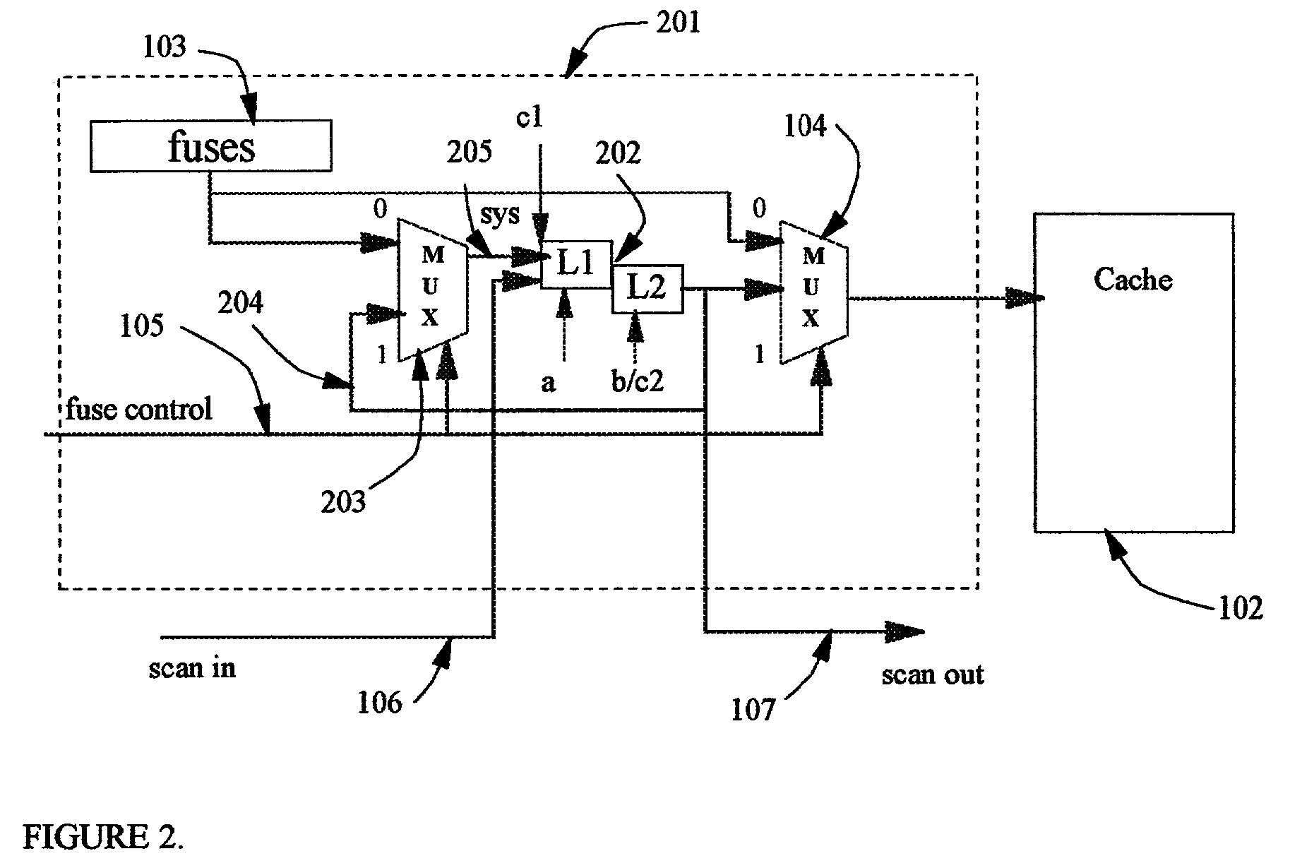
[0005]One invention allows for the updating of programmable fuses while the machine is still running. It allows use of existing cache coherency constructs like congruent class address compare and cache line purge to protect updates in the area of the cache while modified programmable fuse support logic allows for the fuses to be programmed without a machine reboot.
[0006]The invention allows for the testing of circuits using Combined Logic Built-In Self-test (LBIST) and Array Built-in Self-test (ABIST). This invention provides for programmable fuse latches that hold their values during all these complex tests. The method makes use of programmable fuses which contain Level Sensitive Scan Design (LSSD) latches which also have a system port. The system port allows for simpler reading of the fuses as well as for the dynamic updates of the programmable fuses for wordline and other repairs.

Problems solved by technology

These larger cache sizes are making it much more likely to have soft and hard array failures.
However, much of the prior art removes a lot of sets or compartments from the cache.
However, if a wordline failure occurs, all compartments within the wordline may fail and eventually be deleted.
When cache reliability failures occur on machines that are already tested and running, it is not feasible to go back and blow more fuses for the cache failures.
Prior art allowed for separate LBIST and ABIST testing, but the combined test did not work when programmable fuse values were needed in addition to the blown fuses.
Because of the prior art programmable fuse logic, there were some cache test modes that would fail with programmable fuses.

Method used


Image

  • Apparatus and method for programmable fuse repair to support dynamic relocate and improved cache testing
  • Apparatus and method for programmable fuse repair to support dynamic relocate and improved cache testing
  • Apparatus and method for programmable fuse repair to support dynamic relocate and improved cache testing

Examples


Embodiment Construction

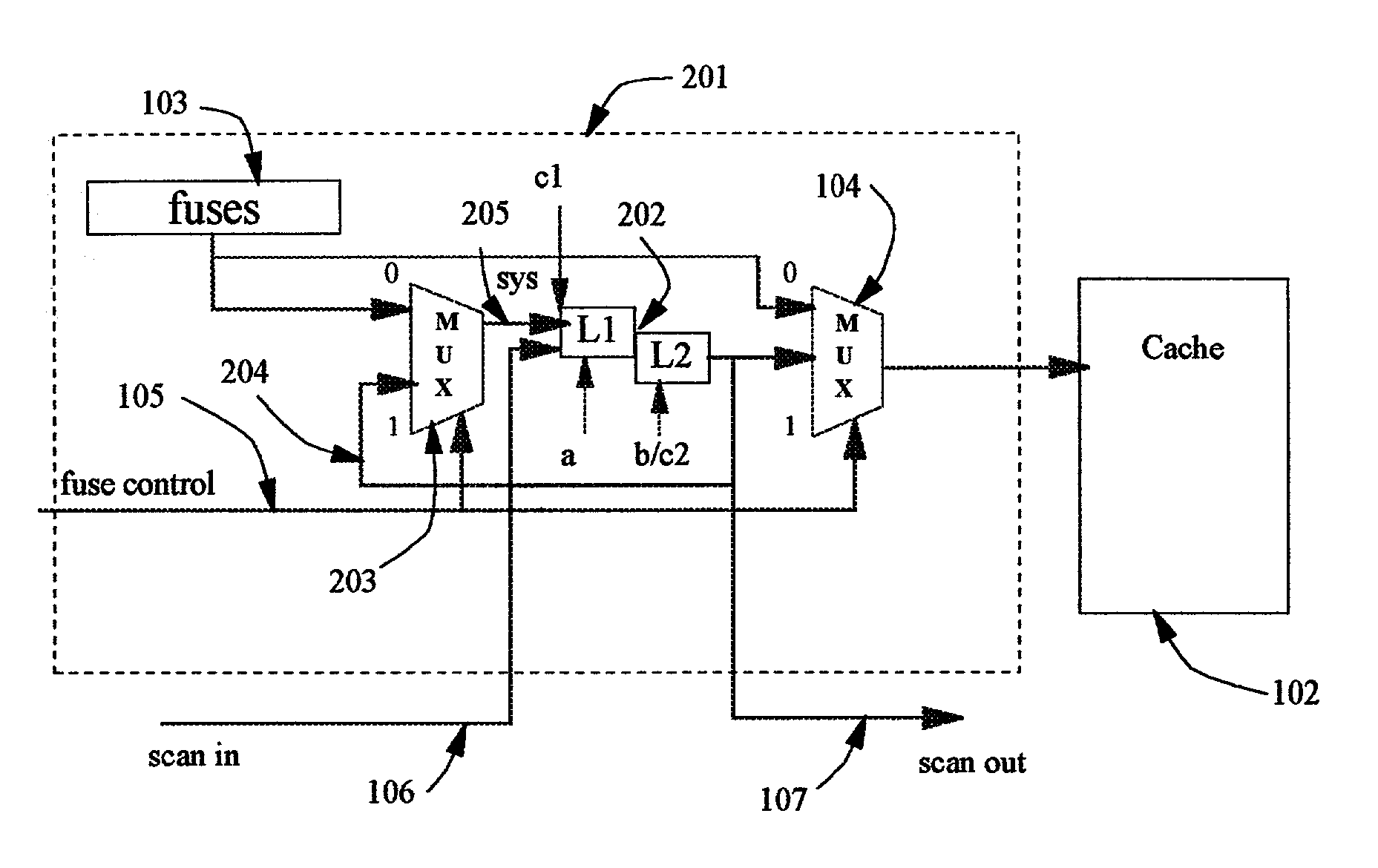
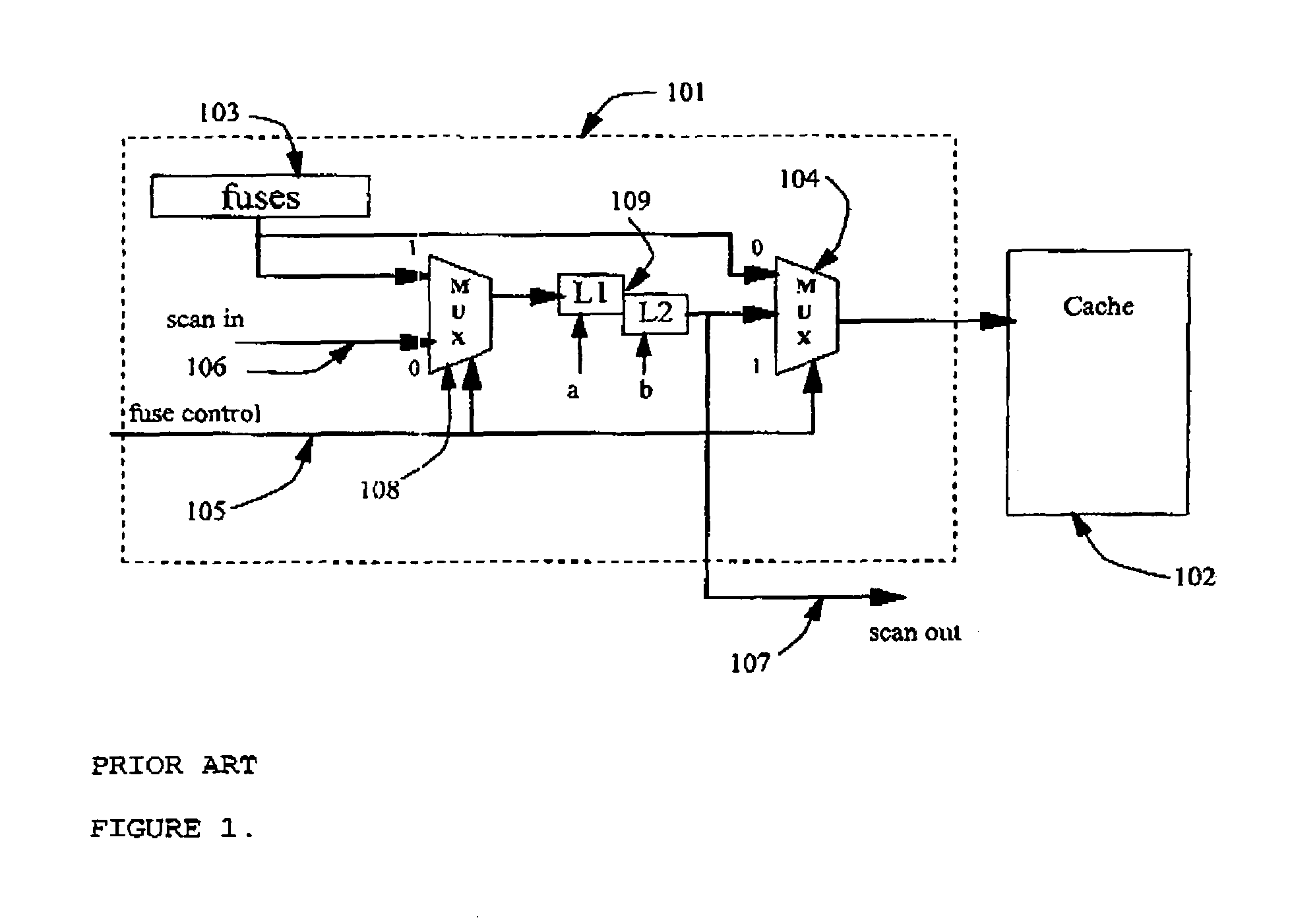
[0015]Turning to FIG. 1, notice that prior art programmable fuse support logic, 101, is used to supply fuse information to the cache, 102. Programmable fuse logic, 101, consists of fuses, 103, that connect to cache, 102, through cache fuse source multiplexer, 104, which selects between blown fuse values, 103, and programmable fuse registers, 109, using fuse control signal, 105. Programmable fuse registers, 109, are scan-only Level-Sensitive Scan Design latches which have a scan input signal, 106, and a scan output signal, 107. There is a scan source multiplexor, 108, which selects between fuses, 103, and scan in signal, 106, using said fuse control signal, 105.

[0016]Whenever the fuse control registers are being scanned, the fuse control signal, 105, is forced to ‘0’ state, which selects the blown fuse values, 103, to the cache using cache fuse source multiplexor, 104. It also selects the scan input signal, 106, as the scan source for the programmable fuse registers, 109. This allows...


PUM


Abstract

An apparatus and method for allowing for dynamic wordline repair in a clock running system in addition to allowing for programmable fuse support of combined Array Built-In Self-Test (ABIST) and Logic Built-In Self-Test (LBIST) testing. The method makes use of programmable fuses which contain Level Sensitive Scan Design (LSSD) latches which also have a system port. The system port allows for simpler reading of the fuses as well as for the dynamic updates of the programmable fuses for wordline and other repairs.

Description

FIELD OF THE INVENTION[0001]This invention relates to symmetrical computer systems, and particularly to cache designs with fuses, fuse controls and line delete, and particularly to an apparatus and method for programmable fuse repair to support dynamically relocating wordlines and other redundant cache circuits with clocks running as well as to support more complex test modes of operation.[0002]Trademarks: IBM® is a registered trademarks of International Business Machines Corporation, Armonk, N.Y., U.S.A. Other names may be registered trademarks or product names of International Business Machines Corporation or other companies.BACKGROUND[0003]As SMP computer systems continue to improve in performance, the cache designs are growing exponentially. These larger cache sizes are making it much more likely to have soft and hard array failures. Previously, a function called set delete was added to remove cache sections that have known defects. However, much of the prior art removes a lot o...

Claims


Application Information

Patent Timeline
Patent Type & Authority Patents(United States)
IPC IPC(8): G01R31/28G11C29/00G01R31/3185
CPCG11C29/78G01R31/318541
Inventor MEANEY, PATRICK J.MCNAMARA, TIMOTHY G.MECHTLY, BRYAN L.
Owner GLOBALFOUNDRIES INC
Learn More