In-building CATV system, down-converter, up-converter and amplifier

Inactive Publication Date: 2006-05-16
MASPRODENKOH KK
View PDF34 Cites 24 Cited by
  • Summary
  • Abstract
  • Description
  • Claims
  • Application Information

AI Technical Summary

Benefits of technology

[0046]As a result, the amplifier has a function as a branch amplifier that can not only amplify upward and downward signals bi-directionally, but also can transmit the reference signal to all the

Problems solved by technology

However when the up-converter used for frequency conversion at the terminal side and the down-converter used for frequency conversion at the connection point between the in-building CATV system and the external bi-directional CATV system are designed to frequency-convert using outputs from respective oscillation circuits for exclusive use, a deviation is generated in the frequency of a frequency-conversion reference signal in each oscillation circuit and so in some cases the in-building upward signal can not be converted to the original upward signal generated by the terminal device.
However, as mentioned above, if the up-conv

Method used


Image

  • In-building CATV system, down-converter, up-converter and amplifier
  • In-building CATV system, down-converter, up-converter and amplifier
  • In-building CATV system, down-converter, up-converter and amplifier

Examples


first embodiment

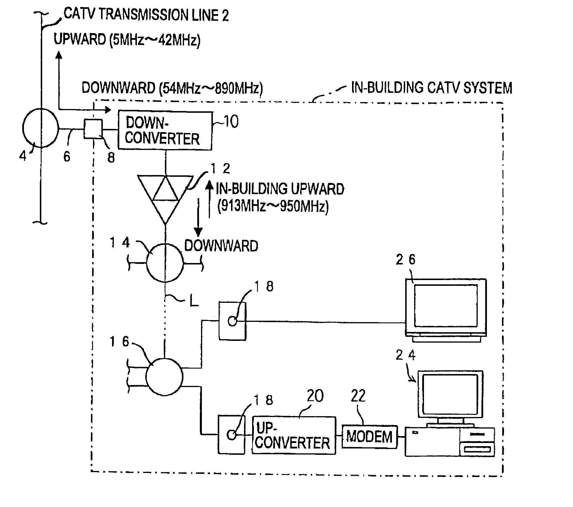
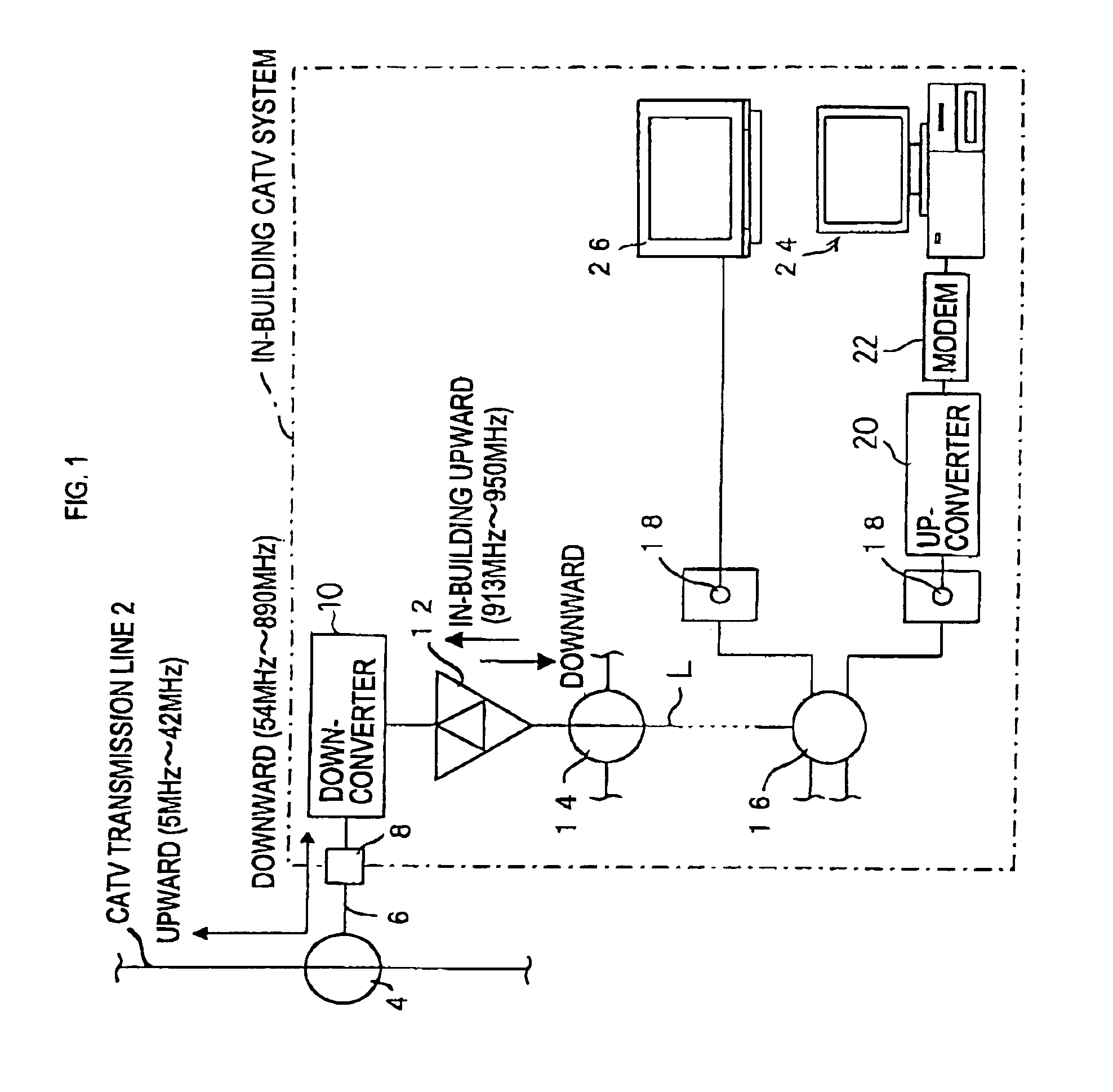
[0060]As shown in FIG. 1, the in-building CATV system of the present embodiment is connected to a lead-in wire 6 branched via a tap unit 4 from a transmission line (CATV transmission line) 2 of an external bi-directional CATV system via a protector 8. A downward signal of the bi-directional CATV system with a frequency of 54 to 890 MHz inputted from the lead-in wire 6 is transmitted to a number of terminals 18 provided in subscriber's houses in a building and consisting of serial units and the like, via a transmission line L made of a coaxial cable in the building, bi-directional amplifiers 12, directional couplers 14, splitters 16 disposed on the transmission line L. Additionally, an in-building upward signal inputted to the terminal 18 via an up-converter 20 described hereinafter is transmitted to the lead-in wire 6. The bi-directional coupler 12 corresponds to an amplifier of the present invention.

[0061]Moreover, in the in-building CATV system of the present embodiment, when the ...

second embodiment

[0145]In the above description, explanation was made for the in-building CATV System which bi-directionally transmits / receives the upward / downward signals between the external bi-directional CATV system and the transmission devices like the down-converter used for constituting the system. However, if a reception antenna of common use for every subscriber is set, for example, on a building to be provided with an in-building CATV system, a reception signal from the reception antenna can be sent to each subscriber via a transmission line of the in-building CATV system.

[0146]Then, thus constituted in-building CATV system will be explained as a second embodiment of the present invention. In the following description, the same constituents as those of the in-building CATV system of the first embodiment are given with the same notations, with detailed explanation thereof being omitted.

[0147]As shown in FIG. 9, the in-building CATV system of the present embodiment is basically constituted a...


PUM


Abstract

In order to correctly perform frequency conversion without using a pilot signal from an external system in a CATV system in which an upward signal is converted to a high frequency in-building upward signal using an up-converter and the in-building upward signal is converted to the original upward signal using a down-converter, there is proposed a down-converter provided with a reference oscillation circuit for generating a reference signal with a frequency lower than that of a downward signal or the in-building upward signal. The in-building upward signal is frequency-converted using the reference signal and the reference signal is transmitted to a transmission line of the terminal side. A bi-directional amplifier on the transmission line can not only amplify the downward signal and the in-building upward signal bi-directionally but also transmit the reference signal to an up-converter of the terminal side. The transmitted reference signal is extracted in the up-converter and the upward signal is frequency-converted to the in-building upward signal.

Description

[0001]This is a continuation-in-part of a application Ser. No. 09 / 507,712 filed Feb. 18, 2000, now U.S. Pat. No. 6,615,407 and entitled “In-Building CATV System, and Up-Converter and Down-Converter for Use therein”.BACKGROUND OF THE INVENTION[0002](i) Field of the Invention[0003]The present invention relates to an in-building CATV system connected to a lead-in wire from an external bi-directional CATV system for transmitting downward signals inputted from the external bi-directional CATV system via an in-building transmission line to plural terminal devices in the building as well as for sending upward signals inputted from each end terminal to the external bi-directional CATV system via the lead-in wire.[0004](ii) Description of the Related Art[0005]In a conventional known in-building CATV system, noises generated in the building are superimposed to the transmission line via subscriber end terminals and the like, and components of the noises with the same frequency as that of the u...

Claims


Application Information

Patent Timeline
IPC IPC(8): H04N7/16H04N7/173H04N7/18
CPCH04N7/102H04N7/17309H04N7/106H04N21/42676
Inventor INAGUMA, MITSUHIKOTORIYAMA, SHIGEMITSUNAKAYAMA, YASUO
Owner MASPRODENKOH KK
Why Eureka
Try Eureka