Method of attaching a self-piercing element in a panel and die member

Inactive Publication Date: 2006-05-23
WHITESELL FORMED COMPONENTS
View PDF12 Cites 21 Cited by
  • Summary
  • Abstract
  • Description
  • Claims
  • Application Information

AI Technical Summary

Benefits of technology

[0016]Because the panel is unsupported in the annular die cavity until the installation is complete and the flange is not driven into the panel bottomed in the die cavity, as described above, the method of this invention substantially eliminates deformation or cold working of the flange portion by the annular punch or plunger which drives the self-piercing element into the die cavity. Further, because of the relative simplicity of the die member, the cost is reduced and die life is improved. Further, because the panel metal is incrementally deformed or “squeezed” into the spaced inwardly concave surfaces on the outer surface of the flange portion, the torque resistance of the self-piercing

Problems solved by technology

It was found, however, that the anti-rotation means disclosed in this patent was insufficient for many applications, including automotive applications.
There remains, however, several problems associated with the use of pockets in the flange portion as disclosed in U.S. Pat. No. 5,020,950.
First, the die surfaces which form the pockets wear, such that the pockets are not always fully formed in the flange portion resulting in insufficient torque resistance.
Second, the self-piercing stud fastener and panel assembly is press sensitive.
That is, if the panel metal is not fully deformed into the pockets, the torque resistance will be inadequate.
Further, the pockets form stress risers in the panel which can become a source of failure of the fastener and panel assembly.
Finally, the use of pockets in the flange portion may provide insufficient torque resistance, particularly where extreme torque resistance is required.
Second, the installation of the self-piercing fastener in a panel is press sensitive.
That is, if the press does not provide sufficient force for full installation, the fastener will be loose in the panel providing insufficient pull-out strength and torque resistance.
However, even where the fastener

Method used


Image

  • Method of attaching a self-piercing element in a panel and die member
  • Method of attaching a self-piercing element in a panel and die member
  • Method of attaching a self-piercing element in a panel and die member

Examples


Example

[0024]As set forth above, this invention relates to an improved self-piercing and clinching male fastener having significantly improved torque resistance, the method of attaching a self-piercing fastener to a panel and an improved female die member. As will be understood by those skilled in this art, the drawings illustrate preferred embodiments of this invention, but are not limiting except as set forth in the appended claims.

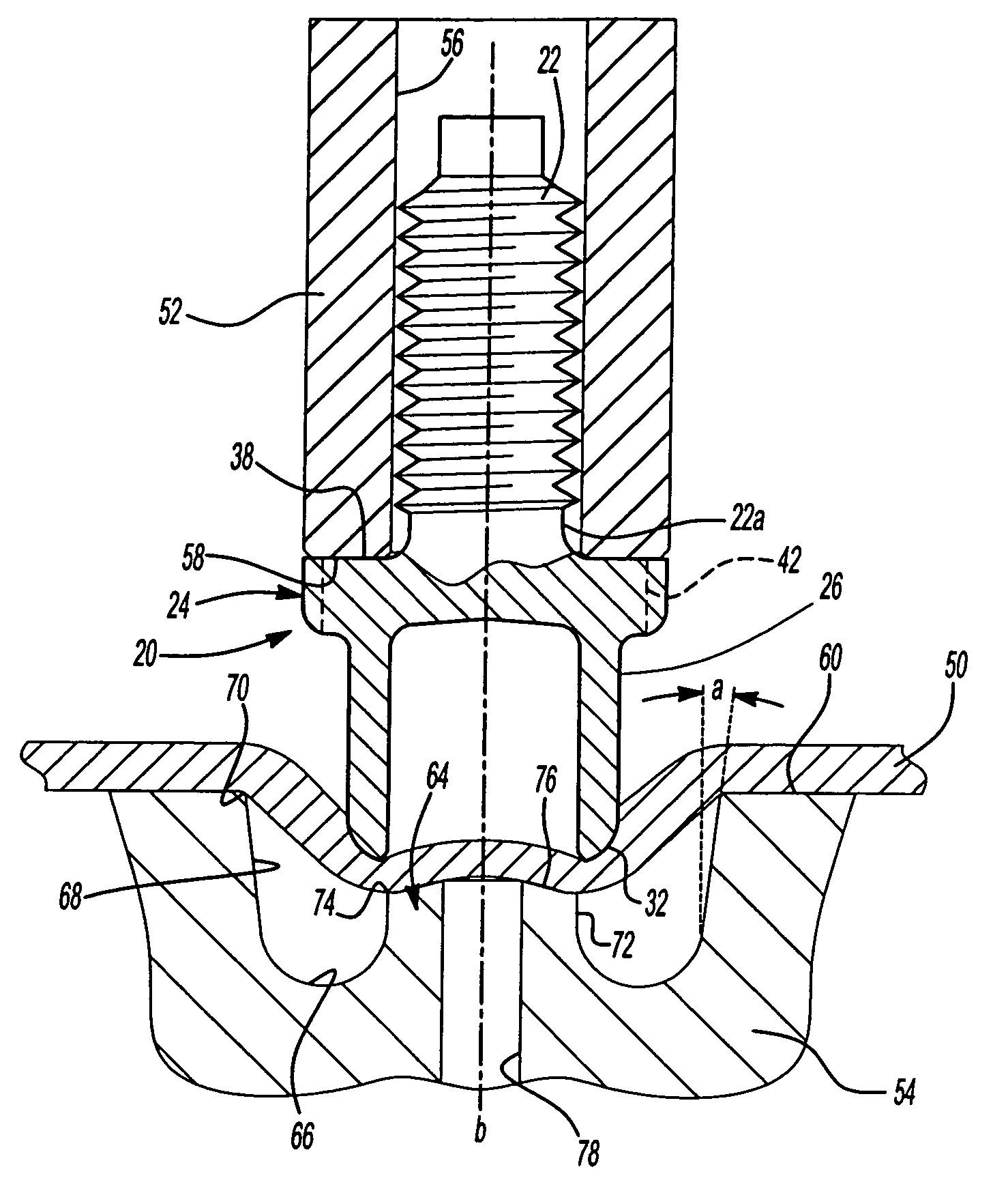
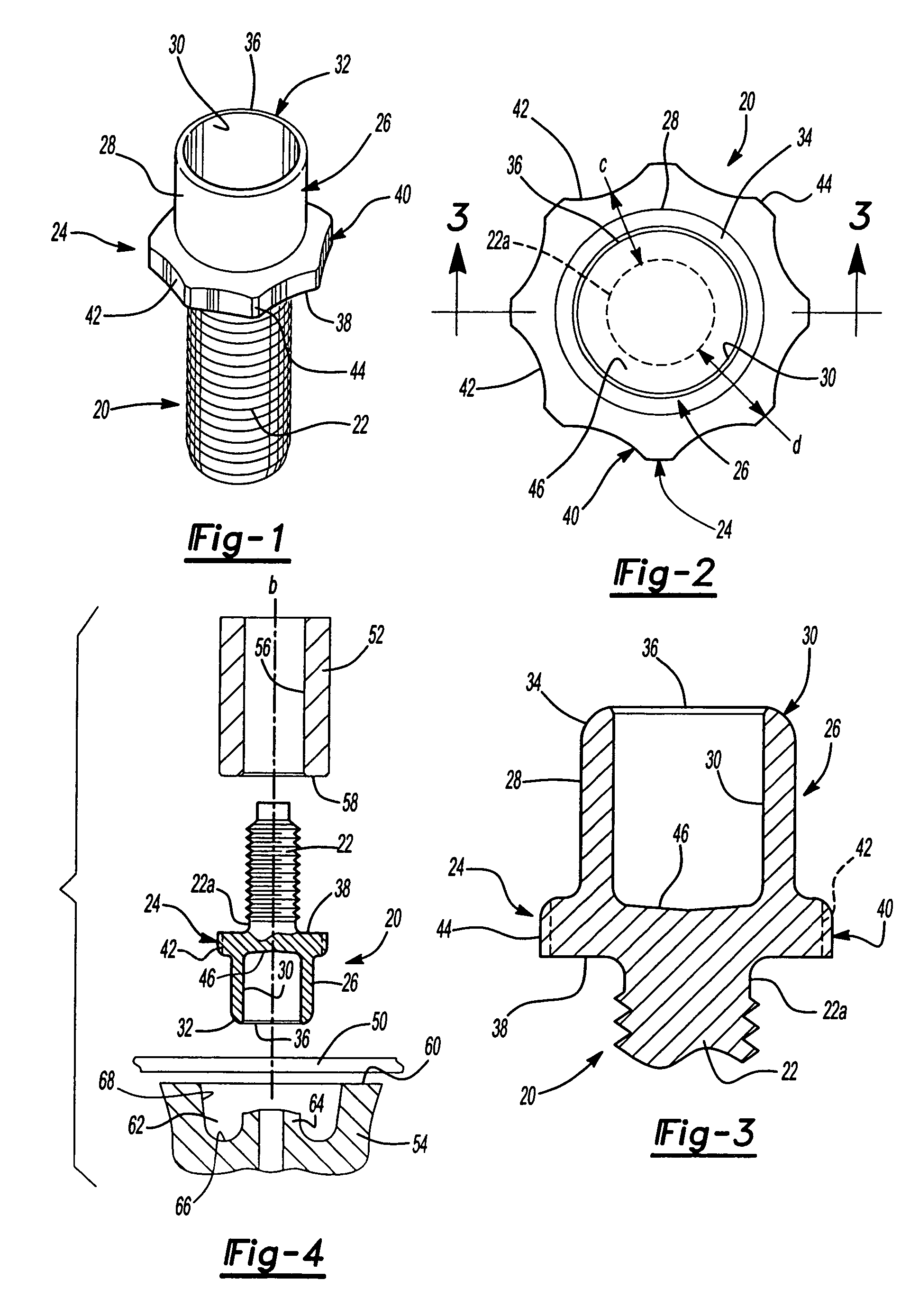
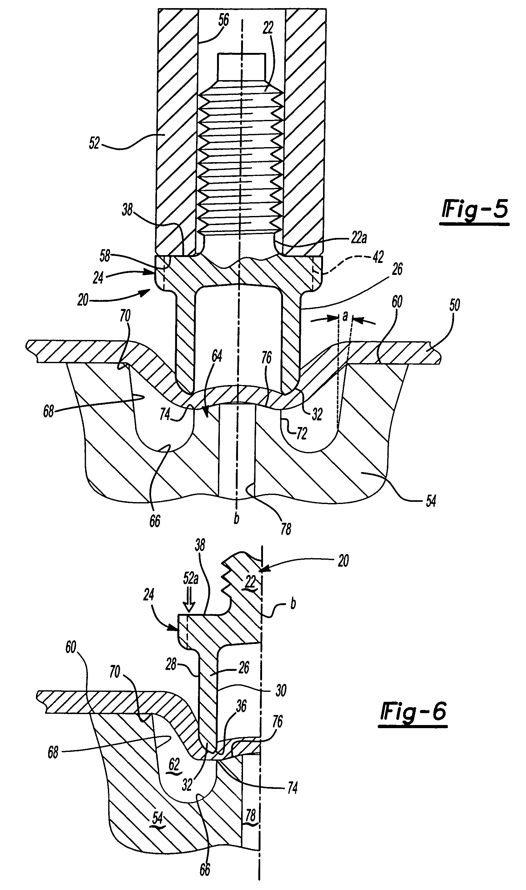
[0025]FIGS. 1 to 3 illustrate one preferred embodiment of the self-piercing and clinching fastener 20 of this invention in the form of a male fastener having a threaded shank portion 22. As will be understood, the stud or shank portion 22 may be threaded or unthreaded and may take various forms. As used herein, the term “fastener” is primarily used to refer to the function of the fastener element, which is to attach a component to the panel or plate to which the self-piercing fastener 20 is attached. The term “self-piercing” refers to the function of the faste...


PUM

PropertyMeasurementUnit
Angleaaaaaaaaaa
Angleaaaaaaaaaa
Angleaaaaaaaaaa

Abstract

A self-piercing element including a shank, a radial flange and a tubular barrel. The flange includes spaced concave surfaces and the annular bearing surface has an area at least four times the concave surfaces. The element is installed in a panel supported on a female die including a central die post, wherein the outer side wall is a frustoconical having an included angle between five and twelve degrees. During installation, the tubular barrel pierces an opening in the panel and the panel is drawn against the outer surface of the tubular barrel and the barrel is deformed into a U-shape. The flange is simultaneously received in the die cavity and the panel is incrementally deformed radially into the concave surfaces between the frustoconical side wall and the flange portion providing improved torque resistance.

Description

[0001]This is a continuation of application Ser. No. 10 / 004,918, filed Dec. 5, 2001 now abandoned.FIELD OF THE INVENTION[0002]This invention relates to a self-piercing element, such as a self-piercing stud having a tubular barrel portion, the method of attachment, and a die member for attaching the self-piercing element to a metal panel.BACKGROUND OF THE INVENTION[0003]Self-piercing and clinching female fasteners such as nuts were developed by the predecessor in interest of the Applicant (Multifastener Corporation) about 50 years ago as disclosed for example in U.S. Pat. No. 2,707,322. Self-piercing and clinching nuts are attached to a metal panel in a die press which may also be used to simultaneously form the panel, wherein generally the upper die platen includes an installation head and the lower die platen includes a die member or die button. Such self-piercing and clinching nuts include a projecting pilot portion which pierces an opening in the panel and the panel metal adjacen...

Claims


Application Information

Patent Timeline
IPC IPC(8): B23P11/00B21J15/00F16B35/04B21J15/30B23P19/06F16B19/08F16B37/04F16B37/06
CPCB23P19/062F16B37/062Y10T29/49954Y10T29/49837Y10T29/49947Y10T29/49915Y10T29/49835Y10T29/53996Y10T29/5343Y10T29/49908
Inventor LADOUCEUR, HAROLD A.
Owner WHITESELL FORMED COMPONENTS
Why Eureka
Try Eureka