Perimeter angle trim

a technology of angle trim and brackets, which is applied in the direction of couplings, rod connections, manufacturing tools, etc., can solve the problems of difficult to hold the bracket level, abutting against a previously installed piece and fastening it to the wall, and not being perfectly rigid, etc., to achieve convenient end-side and lateral registration, less time, and greater positioning accuracy

Active Publication Date: 2006-05-23
USG INTERIORS LLC
View PDF20 Cites 21 Cited by
  • Summary
  • Abstract
  • Description
  • Claims
  • Application Information

AI Technical Summary

Benefits of technology

[0004]The invention provides a wall molding with an extension or formation that enables it to self-align with a previously installed piece. The self-aligning feature permits the wall molding to be installed with less time and greater accuracy in positioning when compared to prior art products. With the self-aligning feature of the invention, the wall molding can be easily registered endwise and laterally with a previously in

Problems solved by technology

In any case, a problem encountered by the installer with conventional wall molding is the difficulty in holding it level and abutted against a previously installed piece and fastening it to the wall all at the same time.
The task is also difficult because the manufactured length of the wall molding is considerable in comparison to its transverse dimensions, so that it is not perfectly rigid.
Additionally, because of

Method used


Image

  • Perimeter angle trim
  • Perimeter angle trim
  • Perimeter angle trim

Examples


Embodiment Construction

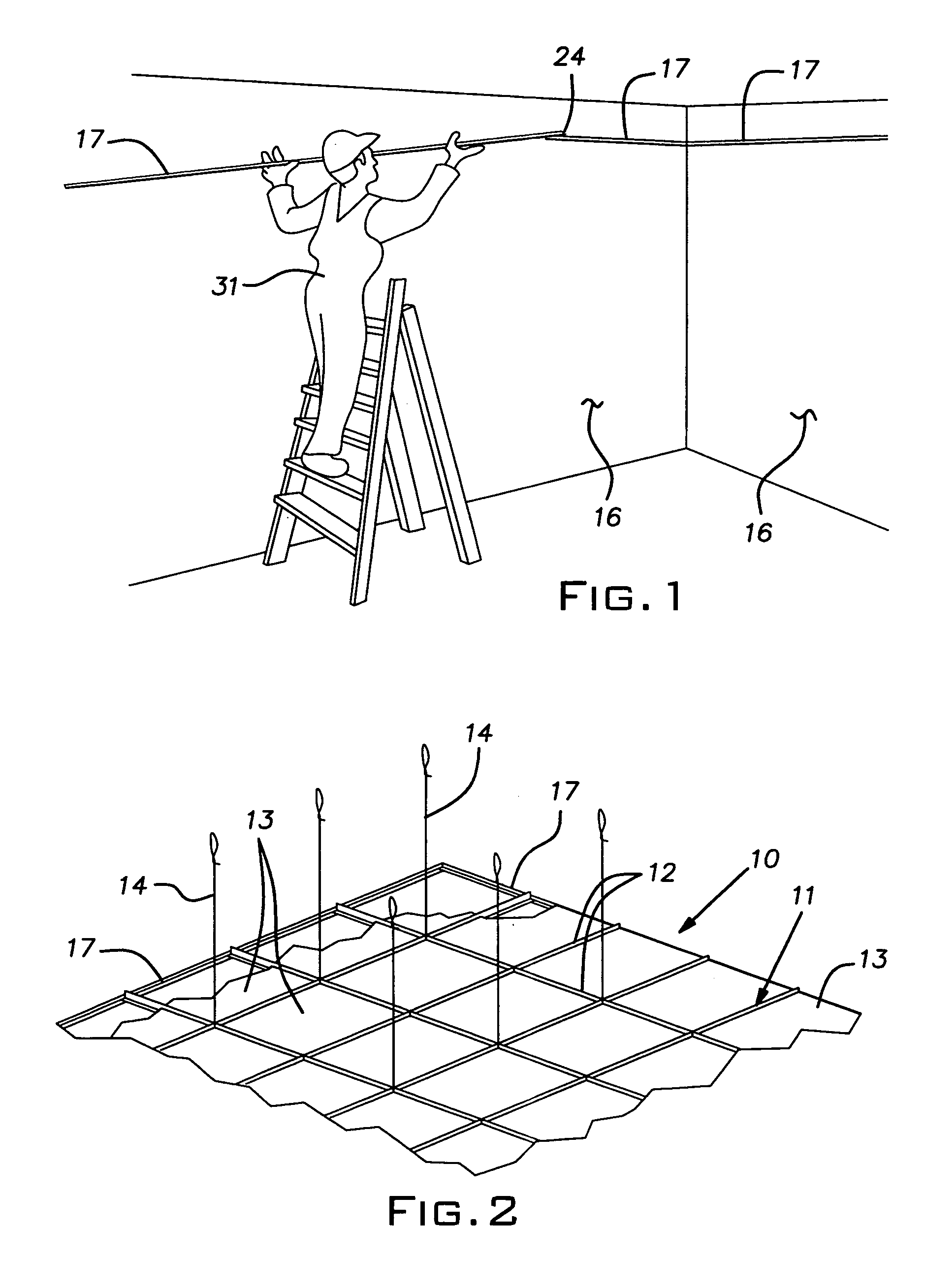
[0011]Referring now to the drawings and in particular to FIG. 2, a conventional suspended ceiling system 10 includes a rectangular grid 11 of inverted metal tees 12 on which is carried rectangular or square lay-in panels or tiles 13. The tees 12 are typically suspended with wires 14 from an overhead superstructure. The edges of the ceiling system, where the ceiling meets the walls, designated 16, of a building, are finished or trimmed with a wall molding 17.

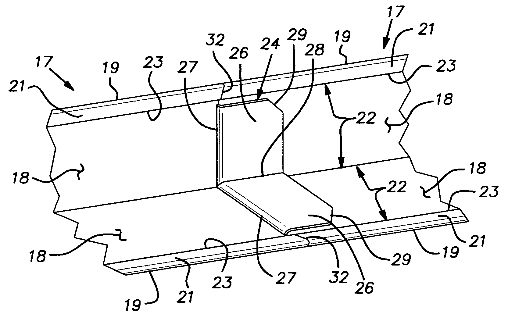
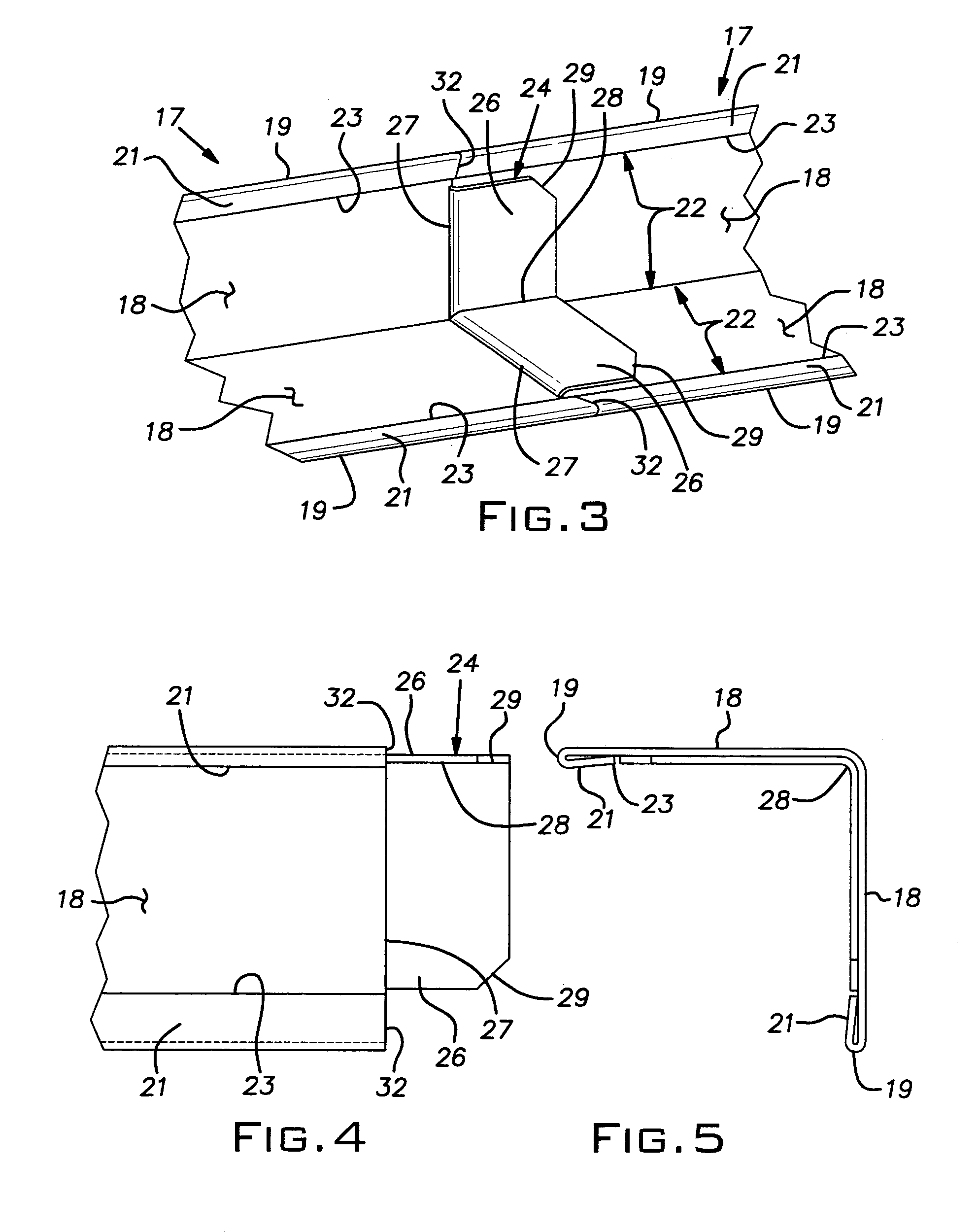
[0012]The wall molding 17 is in the form of a right angle having perpendicular generally planar legs 18 which, in the illustrated embodiment, are of equal width. As is conventional, the wall molding can be manufactured by roll-forming sheet metal, typically steel, which is pre-painted. The legs 18, at their longitudinal free edges 19, have a roll-formed hem 21 where the sheet metal stock is bent back over itself to stiffen the edge and provide a finished appearance. The hem 21 of folded over material normally has a width substant...


PUM


Abstract

A wall molding for suspended ceiling systems has a self-aligning feature adapted to locate one end of a piece being installed on the end of a previously installed piece so that an installation of high quality workmanship is quickly obtained. The self-aligning feature is in the form of a tongue extending longitudinally beyond a faux end and adapted to nest in the previously installed piece. The tongue fits within the spaces between hems on the longitudinal edges of legs of a right angle cross-section and the opposed legs so that the tongue is laterally restrained in the planes of the legs and is longitudinally restrained by abutting end edges.

Description

BACKGROUND OF THE INVENTION[0001]The invention relates to improvements in suspended ceiling componentry and, in particular, to an improved wall molding for suspended ceiling systems.PRIOR ART[0002]Typically, a suspended ceiling includes a wall molding at the intersection of the wall and plane of the ceiling. The wall molding serves to support the edges of ceiling tiles and serves to conceal these edges to provide a finished appearance. The wall molding, typically, can also support the ends of tees comprising the grid carrying the ceiling tiles. Conventional wall moldings are manufactured as elongated angles, typically being roll-formed from strips of prefinished sheet metal. Premium or commercial grade wall angles can have a reinforcing hem along the free edges of their legs. The wall molding or angle ordinarily is installed at the desired height on a wall by suitable fasteners such as screws, nails, staples or the like. The height may be determined by a chalk line, laser level or o...

Claims


Application Information

Patent Timeline
IPC IPC(8): E04C2/38
CPCE04B9/30E04F19/02Y10T403/553Y10T403/55Y10T403/70E04F19/0436
Inventor CALLENS, JEAN-PIERREQUENTIN, GERARD
Owner USG INTERIORS LLC
Why Eureka
Try Eureka