Method of and device for controlling fuel for gas turbine

a technology for controlling fuel and gas turbines, applied in the direction of electric controllers, process and machine control, instruments, etc., can solve problems such as the breakage of the combustion chamber

Active Publication Date: 2006-05-23
MITSUBISHI HITACHIPOWER SYST LTD
View PDF8 Cites 72 Cited by
  • Summary
  • Abstract
  • Description
  • Claims
  • Application Information

AI Technical Summary

Benefits of technology

[0013]The program is used to control the targeted pressure control valve and the fuel for the gas turbine using a computer as a hardware resource. This program forms one element of the computer by a storage that is used in the computer or by a storage medium such as a flexible disk, and functions to input data, perform various arithmetic operations, and to output data. It is thereby possible to realize the gas turbine fuel control method using the computer.

Problems solved by technology

If the input heat changes, then the combustion of a combustor becomes unstable, and combustion vibration may occur to cause the combustor to be broken.

Method used


Image

  • Method of and device for controlling fuel for gas turbine
  • Method of and device for controlling fuel for gas turbine
  • Method of and device for controlling fuel for gas turbine

Examples


Embodiment Construction

[0021]Embodiment of the present invention will be explained in detail below with reference to the accompanying drawings. It should be noted that the present invention is not limited by the embodiment to be explained. It should be also noted that the constituent elements of this embodiment involve constituent elements that a person skilled in the art can easily replace, or those which are substantially equal.

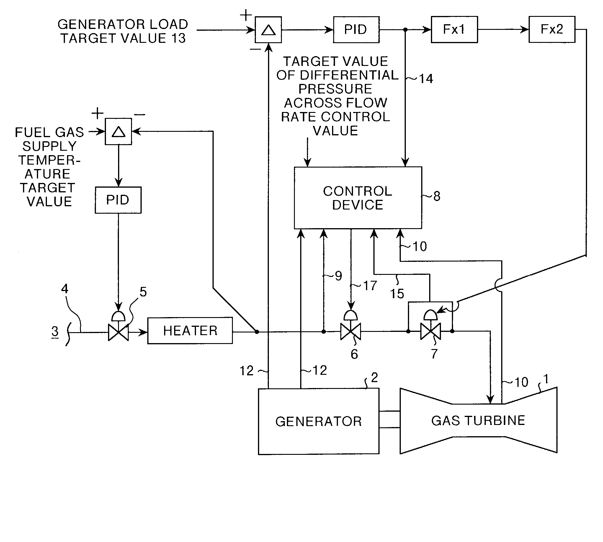
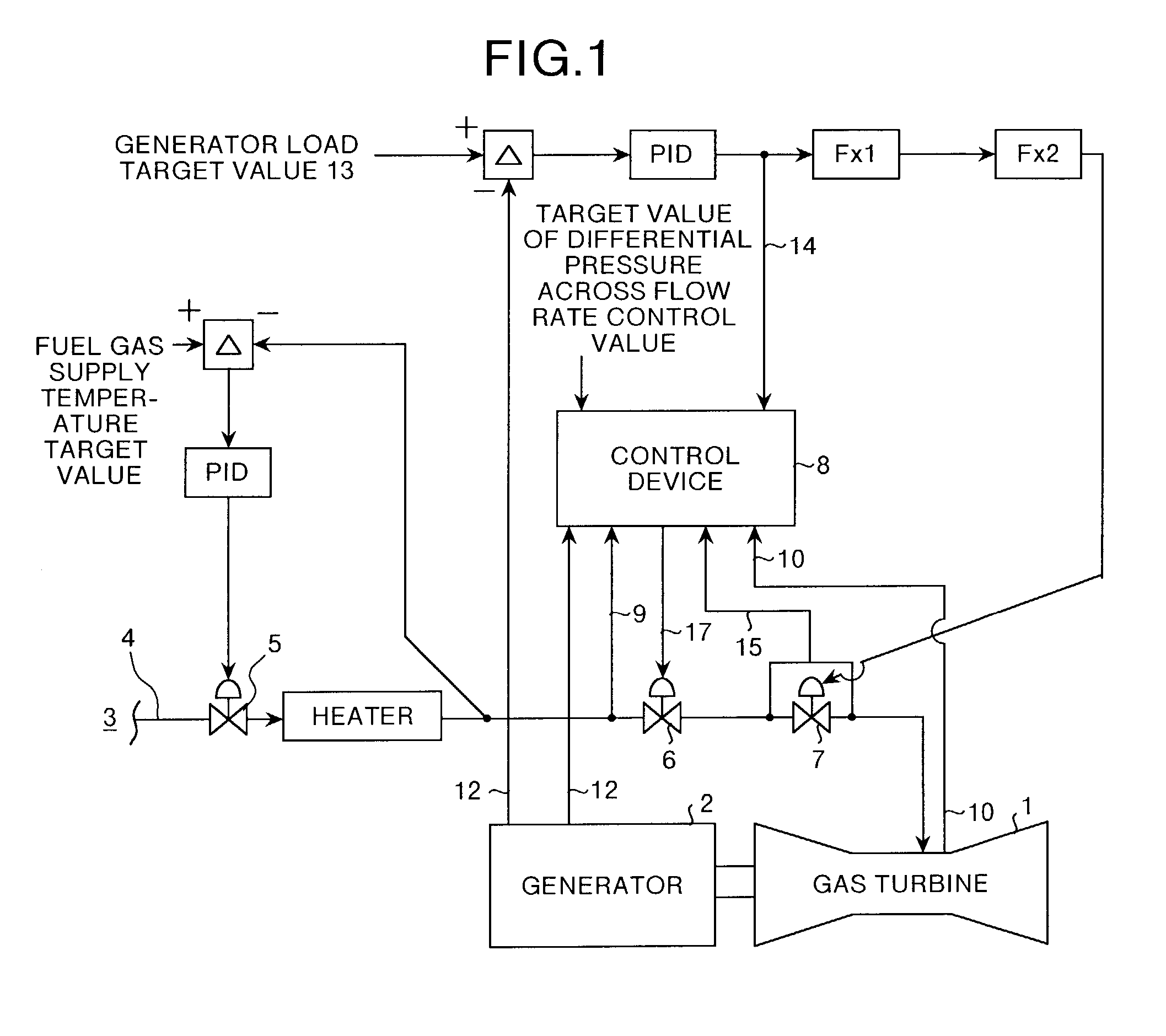
[0022]FIG. 1 is a schematic diagram which shows a method of controlling a flow rate of fuel for a gas turbine in an embodiment of the present invention. This embodiment is the same as the conventional art in that a generator 2 is connected to a gas turbine 1, a piping 4 is provided in an area from a fuel supply source 3 to the gas turbine 1, and the piping 4 is provided with valves such as a temperature control valve 5, a pressure control valve 6, and a flow rate control valve 7. Therefore, the equivalent constituent elements will not be explained herein. Further, since the contr...


PUM


Abstract

Values such as a pressure for supplying fuel gas to a gas turbine, a pressure in a combustor casing of the gas turbine, an output of a generator connected to the gas turbine, and a controlled output for a flow rate control valve are detected by sensors. The detected values are input into a control device. A differential pressure across the flow rate control valve and a target value of the differential pressure are also input into the control device. The control device performs a desired arithmetic operation based on these input values to output a lift instruction for a pressure control valve.

Description

BACKGROUND OF THE INVENTION[0001]1) Field of the Invention[0002]The present invention relates to a technology for controlling fuel for a gas turbine by reflecting changes in a pressure of a gas turbine combustor, an output of a generator, and a controlled output for a flow rate control valve, on a lift amount of a pressure control valve.[0003]2) Description of the Related Art[0004]FIG. 5 is a block diagram showing a conventional method of controlling fuel for a gas turbine. A piping 52 that supplies fuel to a gas turbine 51, is provided in an area from a fuel control source 53 to the gas turbine 51. This piping 52 is provided with a temperature control valve 54, a pressure control valve 55, and a flow rate control valve 56. These valves adjust the flow rate of the fuel that flows in the piping 52. The temperature control valve 54 serves to keep fuel temperature constant. The pressure control valve 55 serves to control a differential pressure. This is because the flow rate control va...

Claims


Application Information

Patent Timeline
Patent Type & Authority Patents(United States)
IPC IPC(8): F02C3/22F02C9/26F02C9/00F02C9/28F02C9/32G05B11/36
CPCF02C9/28F02C9/32F05D2270/301F05D2270/303F05D2270/3015
Inventor TANAKA, SATOSHI
Owner MITSUBISHI HITACHIPOWER SYST LTD
Why Eureka
Try Eureka