Vehicular lock apparatus and method

a vehicular lock and code technology, applied in the direction of cylinder locks, building locks, construction, etc., can solve the problems of assembly line temporary stoppage, pre-coded lock sets, and many problems still exist with conventional vehicular locks, so as to reduce costly vehicle assembly mistakes, eliminate problems, and increase codings

Inactive Publication Date: 2006-05-23
STRATTEC SECURITY
View PDF50 Cites 18 Cited by
  • Summary
  • Abstract
  • Description
  • Claims
  • Application Information

AI Technical Summary

Benefits of technology

[0014]In some cases, the codeable lock embodiments of the present invention are codeable after the lock assembly has been assembled (whether using pivotable two-piece tumblers or otherwise). This capability can provide one or more of the advantages discussed above. As also previously discussed, advantages can be achieved by employing pivotable two-piece tumblers in such embodiments, including the fact that more codings can be enabled by the use of an rotational tumbler path within the confined space of the lock assembly. Other advantages provided by some embodiments include the lack of need for lock sets, elimination of problems associated with tracking the location of locks within a set, and the reduction of costly vehicle assembly mistakes.
[0015]Although not required, the lock assembly according to some embodiments of the present invention can be re-coded to a new code, and in some cases can be re-coded without disassembling the lock assembly, thereby saving considerable cost in re-coding a vehicle if a key is lost or stolen.

Problems solved by technology

Despite numerous developments in vehicular lock technology, several problems still exist with conventional vehicular locks.
Among the most familiar to vehicle manufacturers are problems related to pre-coded lock sets.
This can involve the removal of such vehicles from an assembly line and / or can cause the assembly line to be temporarily stopped.
Thus, the use of pre-coded lock sets can be very costly and time consuming to vehicle manufactures.
Unfortunately, this type of codeable lock design has a number of inherent limitations that limit its feasibility for use in many applications (such as vehicular applications).
One problem with conventional codeable locks is that they normally do not enable enough coding sequences.
Many codeable locks, however, cannot be coded to a large number of different depths of a key, or at least can only be coded to a fraction of the number of possible key depths.
A number of key and lock design considerations limit the number of practical codes for a key.
However, larger numbers of potential codes for a lock normally result in larger numbers of practical codes for the same lock.
Unfortunately, this also makes the lock more susceptible to picking and overpowering and to inadvertent shifting between the two tumbler pieces.
Another significant limitation in conventional codeable locks is related to the linear movement of the two-piece tumblers sometimes employed.
Another problem with conventional codeable locks is that such locks have normally been designed for use in building doors.
To scale the barrel down to the customary size of a barrel on a vehicle (where lock size and weight are typically much greater concerns) would only magnify the problems discussed above.

Method used


Image

  • Vehicular lock apparatus and method
  • Vehicular lock apparatus and method
  • Vehicular lock apparatus and method

Examples


Embodiment Construction

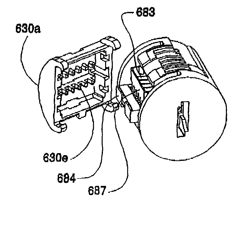
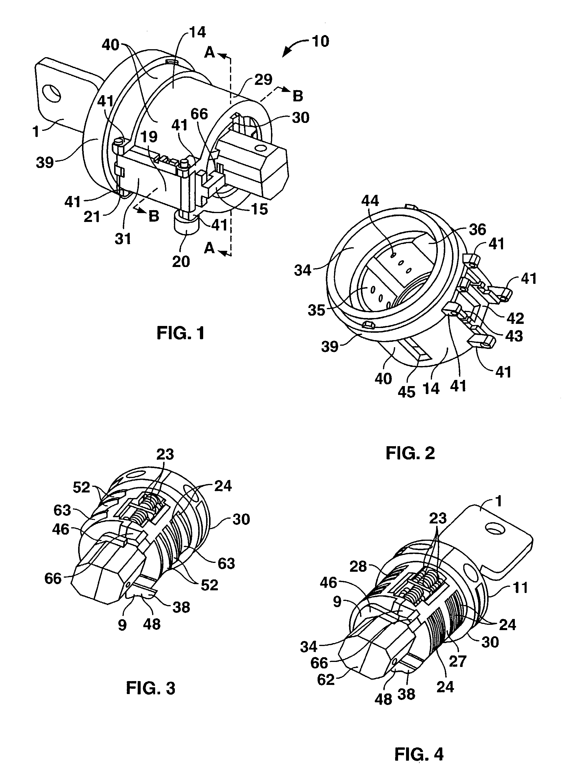
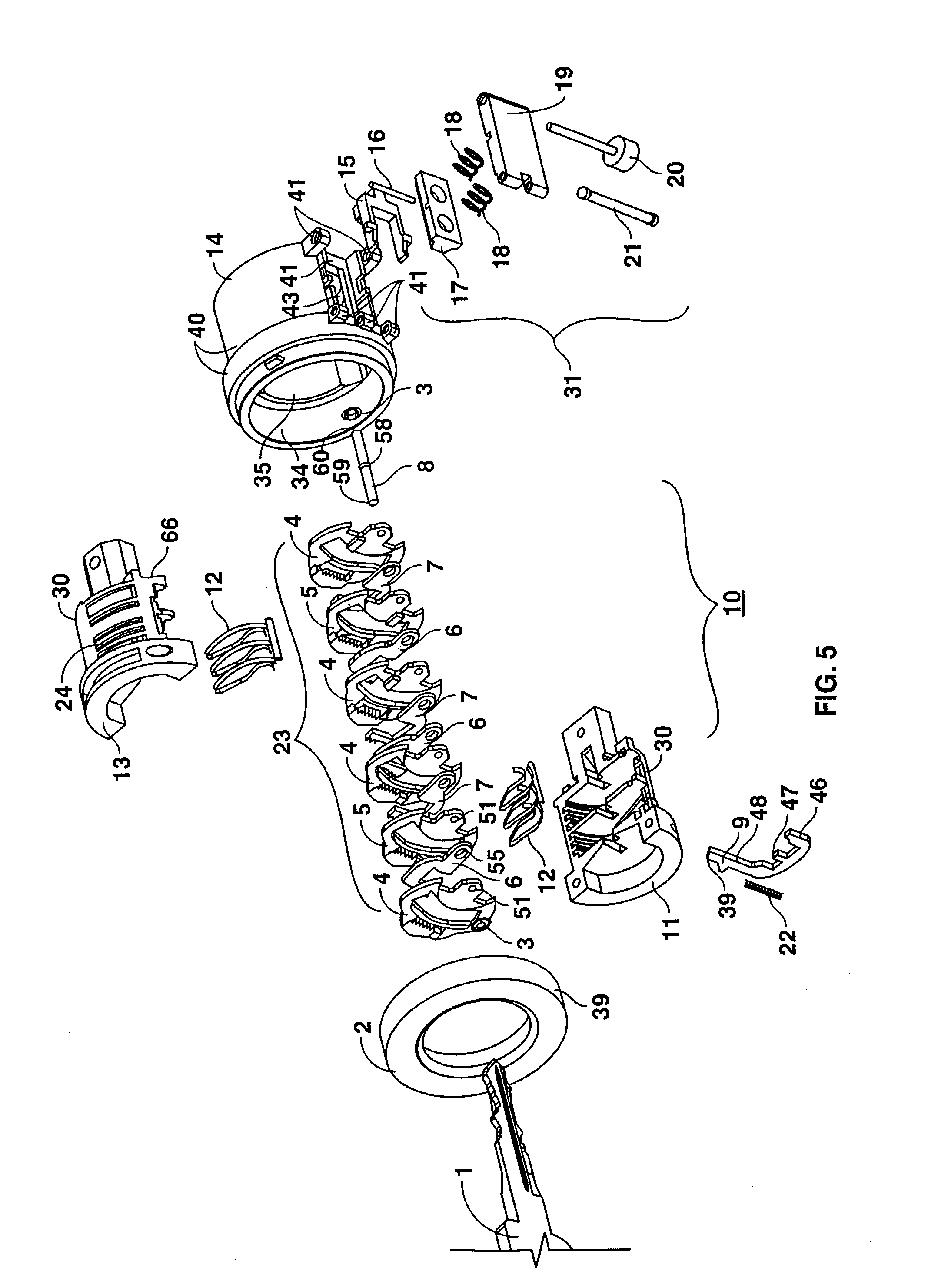
[0081]One embodiment of a lock assembly according to the present invention is illustrated in FIGS. 1–13. With reference first to FIGS. 1–5, the illustrated lock assembly (indicated generally at 29) includes a housing 14, a barrel 30 located within and selectively rotatable with respect to the housing 14, and tumblers 23 coupled for pivotable movement within the barrel 30. By way of illustration, a lock and key set 10 of this nature operates by inserting a properly coded key 1 into a key slot 26 (see FIG. 12) at the end of the barrel 30. As the key 1 enters the barrel 30, the coded surface of the key 1 engages the pivotable tumblers 23, causing a part of each tumbler 23 to pivot. In other embodiments, entry of the key 1 into the barrel 30 causes each tumbler 23 to pivot in its entirety. As used herein, the term “pivotable tumbler” (in its various forms) refers to one-piece tumblers 23 that are pivotable within the lock assembly 29 as well as two-piece or multiple-piece tumblers 23 ha...


PUM


Abstract

In some embodiments, lock assemblies are disclosed which have a housing, a barrel, and at least one tumbler. In some cases, the lock is codeable after the lock assembly has been assembled. Although not required, some embodiments can be re-coded to a new code with and without disassembling the lock assembly. The tumbler(s) can be pivotable, while in other embodiments the tumbler(s) move in a substantially linear fashion. The tumbler(s) can be comprised of two pieces or portions, wherein one piece/portion of the tumbler(s) either directly or indirectly engages the coded surface of a key while the other piece/portion is positionable to prevent rotation of the barrel with respect to the housing. In some embodiments, the tumblers are external to the barrel.

Description

[0001]This application claims the benefit of prior filed co-pending provisional patent application No. 60 / 345,631 filed on Jan. 3, 2002.FIELD OF INVENTION[0002]This invention relates generally to locks and methods of operating locks, and more particularly to codeable vehicular locks and methods for coding vehicular locks.BACKGROUND OF THE INVENTION[0003]Despite numerous developments in vehicular lock technology, several problems still exist with conventional vehicular locks. Among the most familiar to vehicle manufacturers are problems related to pre-coded lock sets. Vehicles are typically provided with a set of locks, such as multiple door locks, a trunk lock, a glove box lock and / or an ignition lock. In most cases, two or more of the locks for a vehicle are operated with a common key. Where multiple locks for a vehicle are coded to the same key, the commonly-coded locks are often sent to a vehicle manufacturer together as a set. During vehicle assembly, these lock sets must be car...

Claims


Application Information

Patent Timeline
Patent Type & Authority Patents(United States)
IPC IPC(8): E05B27/00E05B29/00E05B29/04
CPCE05B29/00E05B29/0066E05B29/004E05B29/0013Y10T70/7446Y10T70/7616Y10T70/7621Y10T70/774
Inventor DIMIG, STEVEN J.ZIRTZLAFF, KEITH D.RITZ, ALAN J.GREEN, THOMAS J.MICOLEY, SCOTT H.KLOS, SCOTT G.MUNZEL, BRIAN J.REIKHER, ALEXANDRE Y.BOESEL, LUCAS J.GRIMMER, LARRY R.WINBERG, RUSSELL J.
Owner STRATTEC SECURITY
Why Eureka
Try Eureka